
MEMS device packaging method and MEMS device packaging structure

A device packaging and device wafer technology, applied in the field of MEMS packaging, can solve problems such as affecting the coverage performance, the inability to bond the top surface of the bonding layer 103', and the uneven surface of the bonding layer 103'.

Pending Publication Date: 2021-09-03
SEMICON MFG ELECTRONICS (SHAOXING) CORP
View PDF0 Cites 1 Cited by
  • Summary
  • Abstract
  • Description
  • Claims
  • Application Information

AI Technical Summary

Problems solved by technology

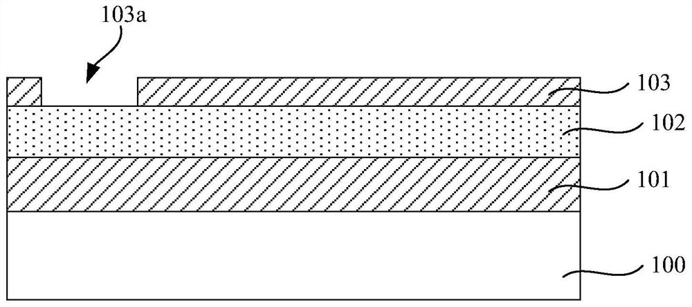
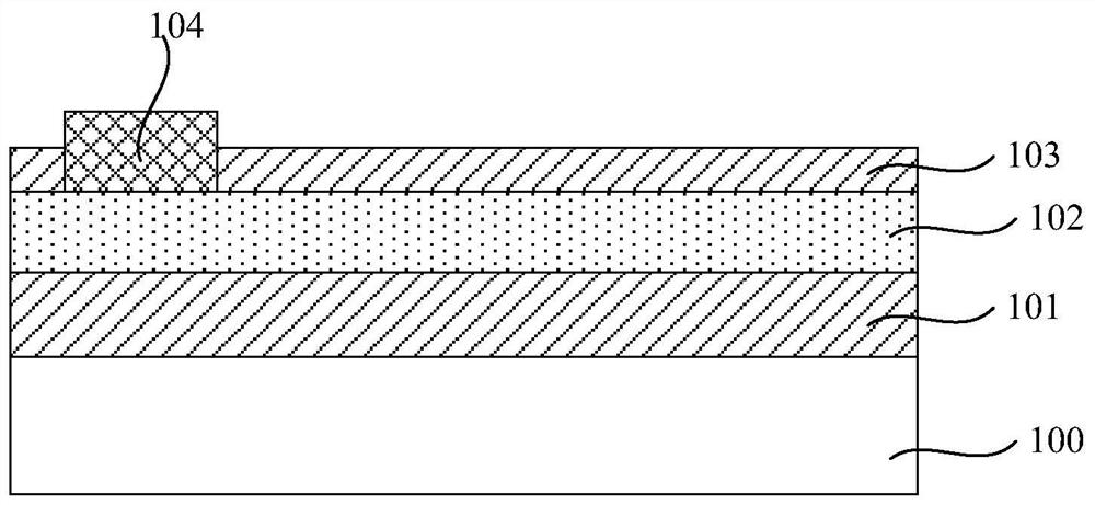
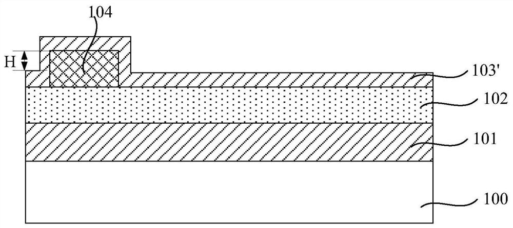
[0011] In the above MEMS device packaging process, please refer to Figure 1C , because after the Al electrode 104 is formed, there is a step difference between the Al electrode 104 and the surface of the device wafer 102 bare chip, this step difference will affect the subsequent re-formed covering on the device wafer 102 bare chip and the surface of the Al electrode 104 The covering performance of the bonding layer 103' causes the surface of the bonding layer 103' to be uneven, and there will still be a height difference H1 between the bonding surface of the bonding layer 103' and the top surface of the Al electrode 104, and because The Al electrode 104 is pre-formed and required to have a corresponding height, which makes it impossible to planarize the top surface of the bonding layer 103' after covering the bonding layer 103'
Please refer to Figure 1D , the top surface of the bonding layer 103' cannot be planarized, which will lead to depressions on the bonding surface of the bonding layer 103' after the bonding layer 103' and the device wafer 102 are etched to form the lower comb structure 102a or bump 103b; refer to Figure 1E and Figure 1F , after the cover wafer 105 and the device wafer 102 are bonded, there will be voids at the bonding interface between the cover wafer 105 and the device wafer 102, and these voids will reduce the cover wafer 105 and the device wafer 102 bonding reliability, and then when the bonding layer 103' on the lower comb structure 102a of the device wafer 102 is etched and removed by VHF, the bonding layer 103' at the cavity of the bonding interface will be Undercutting (that is, lateral etching) increases the cavity, thereby forming a gap 103c on the bonding interface, and the gap 103c will cause the problem that the cover wafer 105 is peeled off from the device wafer 102
[0012] Additionally, please refer to Figure 1B , the formation of the Al electrode 104 needs to be achieved through deposition, photolithography and etching processes, and please refer to Figure 1E and 1F , it is also necessary to use the mask of the Al electrode again to carry out corresponding photolithography and etching to open the electrode lead-out frame of the cover wafer 105 from the side of the cover wafer 105 facing away from the device wafer 102, so as to form an exposed The opening 105b of the bonding layer 103' on the top surface of the Al electrode 104 and the Al electrode 104 is subsequently removed. Obviously, the Al electrode exposed by the cover wafer 105 needs to be formed. 104. It is necessary to use the mask of the Al electrode twice for photolithography and etching, the process is complicated and the cost is high

Method used


Image

  • MEMS device packaging method and MEMS device packaging structure
  • MEMS device packaging method and MEMS device packaging structure
  • MEMS device packaging method and MEMS device packaging structure

Examples


Embodiment Construction

[0040] The technical solutions proposed by the present invention will be described in further detail below in conjunction with the accompanying drawings and specific embodiments. The advantages and features of the present invention will become clearer from the following description. It should be noted that all the drawings are in a very simplified form and use imprecise scales, and are only used to facilitate and clearly assist the purpose of illustrating the embodiments of the present invention.

[0041] Please refer to figure 2 , an embodiment of the present invention provides a MEMS device packaging method, comprising the following steps:

[0042] S1, providing a device wafer, covering the surface of the device wafer with a bonding medium layer, and planarizing the top surface of the bonding medium layer;

[0043] S2, etching the bonding medium layer to form electrode grooves in the bonding medium layer;

[0044] S3, forming an electrode in the electrode groove by using...


PUM


Abstract

According to an MEMS device packaging method and an MEMS device packaging structure provided by the invention, after the surface of a device wafer is covered with a bonding dielectric layer and before the bonding dielectric layer is etched to form an electrode groove, the top surface of the bonding dielectric layer is flattened, so that the flatness of the surface, used for bonding, of the bonding dielectric layer can be improved. According to the invention, a cavity is prevented from being generated between the bonded cover plate wafer and a corresponding bonding interface, so that the lateral etching amount of the bonding dielectric layer at the bonding interface during subsequent removal of the bonding dielectric layer between two wafers is reduced, the bonding reliability is further ensured, and stripping of the cover plate wafer is avoided. Moreover, since the stripping process is used to form an electrode in the electrode groove, the step of etching an electrode layer can be omitted before bonding, and the top of the formed electrode is no longer covered with a redundant bonding dielectric layer, so that the process is simplified, the cost is reduced, and the formation of the electrode can also be ensured not to influence the surface flatness of the bonding dielectric layer which is formed in advance.

Description

technical field [0001] The invention relates to the technical field of MEMS packaging, in particular to a MEMS device packaging method and packaging structure. Background technique [0002] Micro-Electronic-Mechanical-System (MEMS) packaging technology is an important research direction in the field of MEMS research. On the one hand, packaging can prevent MEMS devices from being affected by dust, moisture, etc. The internal damping of the MEMS device can also be changed through vacuum or airtight packaging to improve the performance of the product. [0003] Wafer-level packaging technology is the main solution to achieve high performance, low cost and mass production of MEMS devices. It is mainly to add a cap (Cap) on each MEMS device (Device) and bond the two to complete the package. , including the following steps: [0004] First, please refer to Figure 1A , after bonding the device wafer 102 bare chip to the substrate wafer 100 through a bonding layer 101 such as silic...

Claims


Application Information

Patent Timeline
IPC IPC(8): B81C1/00B81B7/00B81B7/02
CPCB81C1/00261B81C1/00269B81B7/0032B81B7/02B81C2203/0109B81C2203/0118B81B2201/02B81B2201/0235B81B2201/0242B81B2201/0271B81B2203/04B81B2207/09
Inventor 王晓东刘国安
Owner SEMICON MFG ELECTRONICS (SHAOXING) CORP
Learn More