
An integrated high-frequency intelligent leveling machine and its working method

An integrated, leveling machine technology, applied in the direction of forming tools, manufacturing tools, metal processing, etc., can solve the problems that the efficiency of electromagnetic induction cannot be guaranteed, the effect of heating is affected, and the matching of power supply capacity and inductance is difficult, and the effect of heating can be improved. , Improve heating efficiency, and apply to a wide range of effects

Active Publication Date: 2021-12-28
JIANGSU UNIV OF SCI & TECH
View PDF0 Cites 0 Cited by
  • Summary
  • Abstract
  • Description
  • Claims
  • Application Information

AI Technical Summary

Problems solved by technology

[0004] (1) The induction heater and the power supply are separated, and the induction heating coil is fixed on the mobile trolley, so that the induction coil and the power supply are generally connected through a long cable, and the loss of high-frequency current in the cable is relatively large. At the same time, it is difficult to match the capacitance and inductance of the power supply
[0005] (2) Generally, when the distance between the induction heating coil and the steel plate is 3-4mm, the effect of electromagnetic induction is the best, but the distance between the traditional induction coil and the heating component and the steel plate will not be adjusted with the deformation of the steel plate. The efficiency of electromagnetic induction cannot be guaranteed, thus affecting the heating effect
[0006] (3) Both the power supply and the coaxial transformer adopt water cooling to dissipate heat, and the inside of the power supply is prone to water leakage, causing potential safety hazards

Method used


Image

  • An integrated high-frequency intelligent leveling machine and its working method
  • An integrated high-frequency intelligent leveling machine and its working method
  • An integrated high-frequency intelligent leveling machine and its working method

Examples


Embodiment Construction

[0039] The present invention will be further illustrated below in conjunction with the accompanying drawings and specific embodiments, and it should be understood that these embodiments are only for illustrating the present invention and are not intended to limit the scope of the present invention.

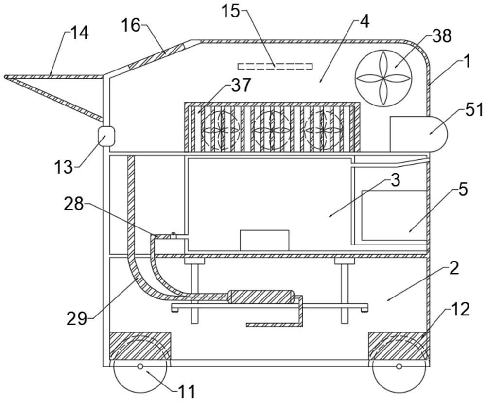
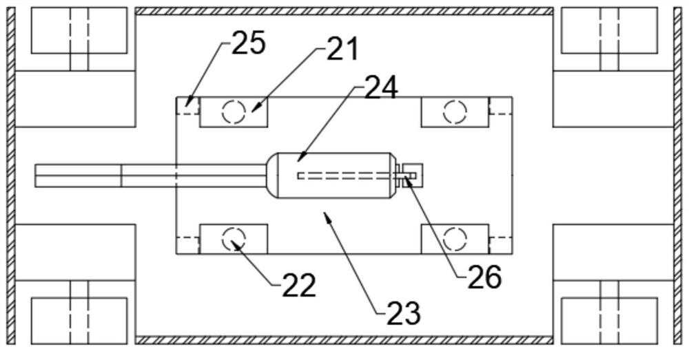
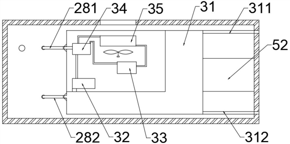
[0040] An integrated high-frequency intelligent leveling machine, such as Figure 1~4 As shown, it includes an integral frame 1 divided into a three-layer structure, and an intelligent heating mechanism 2 arranged on the lower layer of the integral frame 1, a chiller mechanism 3 and a main controller 5 in the middle layer, a high-frequency power supply mechanism 4 in the upper layer, The air-cooling system, the high-definition camera 51, and the layers of the overall frame 1 are separated by steel plates and have via holes on the steel plates to facilitate the layout of signal lines and various pipelines. The overall casing of the leveler is made of plastic material to avoid the m...


PUM


Abstract

The invention discloses an integrated high-frequency intelligent leveler. The overall leveler frame is divided into three-layer frames, which are respectively an intelligent heating mechanism, a chiller mechanism and a high-frequency power supply mechanism. The three-layer frame is controlled by a main controller. Coordinated control. The overall leveler frame includes two pairs of wheels driven by a servo motor, a push rod at the rear and upper part of the power frame, a control panel installed in front of the push rod, and a three-phase AC socket for power supply work under the push rod. and discloses its working method. Through the integrated structural design of intelligent heating mechanism, chiller mechanism and high-frequency power supply mechanism, the high-frequency current generated by the resonant circuit can be directly transmitted to the high-frequency transformer on the lifting platform without long-distance cable transmission. For high-frequency transformers, the transmission distance of high-frequency and high-voltage current is shortened from tens of meters to less than 1 meter, which not only reduces the manufacturing cost, but also greatly reduces the energy loss in the transmission process.

Description

technical field [0001] The invention relates to an electromagnetic induction heating leveling device for thin plate structures of ships and ocean engineering, in particular to an integrated high-frequency intelligent leveling machine and a working method thereof. Background technique [0002] At present, ships and ocean engineering structures are mainly connected by fusion welding. The uneven local heating of steel by welding arc will inevitably lead to stress and deformation of ships and ocean engineering structures. There are many problems in the traditional pyrotechnic leveling and deformation process, such as high requirements for the experience of the operator, high uncertainty of the leveling effect, and toxic gas will be generated during the heating process, which has a great impact on the environment. There will also be safety hazards when the fuel is stored. In addition, water and fire correction has high labor intensity and poor environment, and fewer and fewer pe...

Claims


Application Information

Patent Timeline
Patent Type & Authority Patents(China)
IPC IPC(8): B21D1/00B21D37/16B21C51/00
CPCB21D1/00B21D37/16B21C51/00
Inventor 吴百公王贤健许静王秋平谷家扬
Owner JIANGSU UNIV OF SCI & TECH
Learn More