Electrostatic field assisted laser additive manufacturing device and method

An auxiliary laser and additive manufacturing technology, which is applied in the directions of additive processing, process efficiency improvement, and energy efficiency improvement, and can solve the problems of difficulty in adjusting the internal composition and performance of the workpiece

Pending Publication Date: 2021-09-07
NINGBO INST OF MATERIALS TECH & ENG CHINESE ACADEMY OF SCI
View PDF6 Cites 0 Cited by
  • Summary
  • Abstract
  • Description
  • Claims
  • Application Information

AI Technical Summary

Problems solved by technology

[0004] In order to solve the above technical problems, this application proposes an electrostatic field assisted laser additive manufacturing device and method, and then at least to a certain extent overcomes the problems such as the difficulty in regulating the internal composition and performance of the workpiece due to the limitations and defects of related technologies

Method used


Image

  • Electrostatic field assisted laser additive manufacturing device and method
  • Electrostatic field assisted laser additive manufacturing device and method
  • Electrostatic field assisted laser additive manufacturing device and method

Examples


Embodiment 1

[0112] In this example, the DC power supply is used as the power supply for the field, the direction along which the molten pool is formed is the application direction of the electrostatic field, the fiber laser with a wavelength of 1064 nm is used as the light source for laser additive manufacturing, and the laser beam adopts a Gaussian beam. The specific process is as follows:

[0113] Step 1. Select 304 stainless steel as the substrate to be clad, with a size of 200mm×200mm×10mm, and the additional material (cladding powder) is stainless steel 316L metal powder, with a particle size of 75-150μm;

[0114] Step 2, the pretreatment of the substrate to be clad and the metal powder, the substrate to be melted is polished with sandpaper, then the oil stains are removed with anhydrous ethanol, dried, and the metal powder is dried;

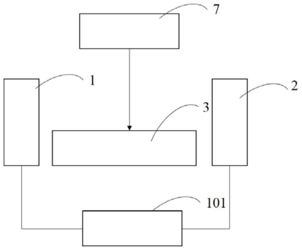
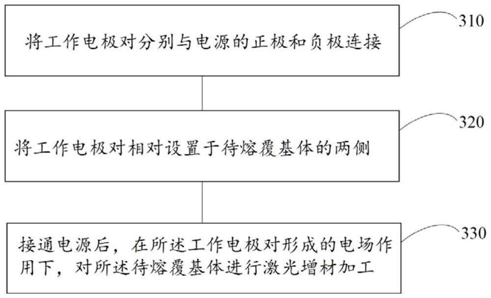
[0115] Step 3. The working electrode pairs are relatively arranged on both sides of the horizontal plane of the substrate to be clad vertically, and i...

Embodiment 2

[0120] In Example 2, the raw materials and process parameters for laser additive manufacturing are the same as those in Example 1, except that there is no electrostatic field assistance.

[0121]The samples of the clad substrates in Example 1 and Example 2 were cut along the scanning direction, and observed and characterized after grinding and polishing. Figure 10-11 The scanning electron microscope image and the metallographic image of the cross section of the cladding layer without the assistance of the electrostatic field in Example 2 are respectively shown, Figure 12-13 The scanning electron microscope image and the metallographic image of the cross section of the cladding layer with the assistance of the electrostatic field in Example 1 are shown. Compared Figure 10 and Figure 12 It can be seen that with the assistance of the electrostatic field (the strength of the electrostatic field is 133V / cm), the number of pores in the section of the cladding layer is signific...


PUM

PropertyMeasurementUnit
wavelengthaaaaaaaaaa

Abstract

The invention discloses an electrostatic field assisted laser additive manufacturing device and method. The electrostatic field assisted laser additive manufacturing device at least comprises a power source, working electrode pairs and a laser. The working electrode pairs are correspondingly connected with the positive electrode and the negative electrode of the power source; and the laser is used for performing laser additive machining on a to-be-cladded base body between the working electrode pairs under the action of an electrostatic field formed by the working electrode pairs. According to the electrostatic field assisted laser additive manufacturing device, in the laser additive machining process, the working electrode pairs can provide the electrostatic field for the to-be-cladded base body located between the working electrode pairs, and under the action of the electrostatic field, elimination of holes in a workpiece in the manufacturing process and regulation and control of the trend of the internal structure of the workpiece can be achieved.

Description

technical field [0001] The application belongs to the technical field of material preparation, and in particular relates to an electrostatic field assisted laser additive manufacturing device and an electrostatic field assisted laser additive manufacturing method. Background technique [0002] Laser additive manufacturing technology is based on the idea of ​​calculus. It uses laser layered scanning and superposition molding to increase materials layer by layer, and convert digital models into three-dimensional solid parts. Traditional metal parts molding and manufacturing use the casting method. The solid metal is melted into a liquid state and poured into a mold of a specific shape and then solidified. It has many processes, high mold cost, long cycle from design to parts manufacturing, and has a complex inner cavity. The disadvantage of the powerlessness of the parts of the structure. Compared with traditional casting technology, laser additive manufacturing technology is...

Claims


Application Information

Patent Timeline
Patent Type & Authority Applications(China)
IPC IPC(8): B22F3/105B33Y30/00B33Y10/00
CPCB33Y30/00B33Y10/00B22F2999/00Y02P10/25
Inventor 欧阳文泰徐子法焦俊科张文武
Owner NINGBO INST OF MATERIALS TECH & ENG CHINESE ACADEMY OF SCI
Why Eureka
Try Eureka