Check patentability & draft patents in minutes with Patsnap Eureka AI!

CO2 transcritical parallel compression refrigeration system and control method

A compression refrigeration and control method technology, which is applied in the direction of refrigerators, compressors, compressors, etc., can solve the problem that the system deviates from the optimal performance point, and achieve the effect of improving system performance

Active Publication Date: 2021-09-07
XI AN JIAOTONG UNIV +1
View PDF9 Cites 1 Cited by
  • Summary
  • Abstract
  • Description
  • Claims
  • Application Information

AI Technical Summary

Problems solved by technology

[0004] The object of the present invention is to provide a CO 2 The control method of the transcritical parallel compression refrigeration system is to solve the optimization problem of the optimal exhaust pressure, intermediate pressure and volume flow ratio of the parallel compression system, and in the actual operation process, due to the change of the ambient temperature, the system deviates from the optimal performance point of view

Method used


Image

  • CO2 transcritical parallel compression refrigeration system and control method
  • CO2 transcritical parallel compression refrigeration system and control method
  • CO2 transcritical parallel compression refrigeration system and control method

Examples


Embodiment 1

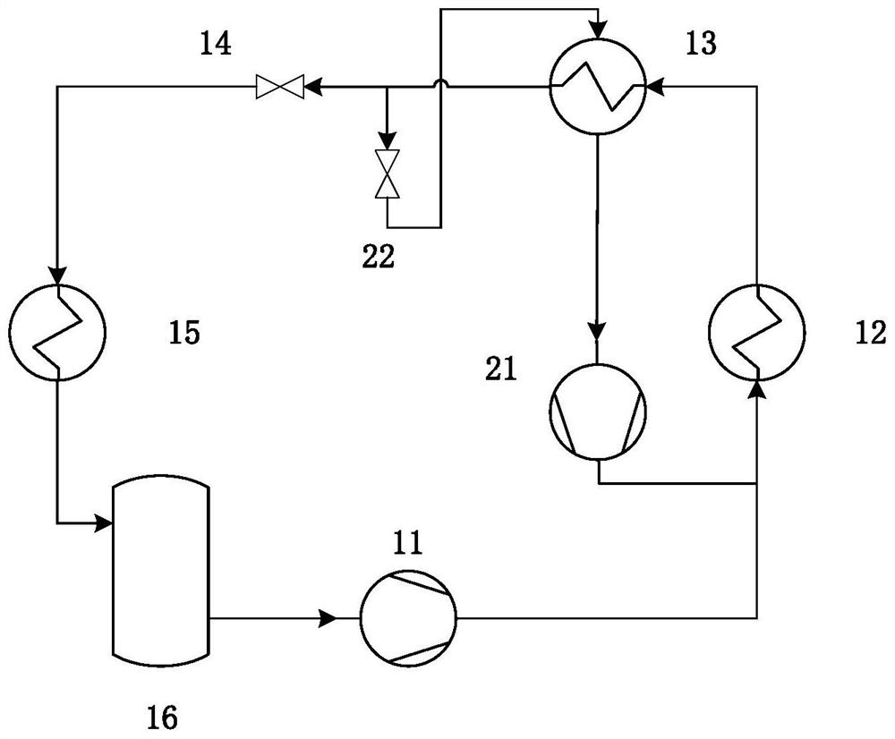
[0070] see figure 1 As shown, the present invention provides a CO 2 Transcritical parallel compression refrigeration system, including: main channel transcritical CO 2 Cyclic and branch near-critical CO 2 cycle device.

[0071] main road transcritical CO 2 The circulation device includes a main compressor 11 , a gas cooler 12 , a regenerator 13 , a main road throttling valve 14 , an evaporator 15 and a gas-liquid separator 16 which are sequentially connected in circulation.

[0072] branch near critical CO 2 The cycle includes a bypass throttle valve 22 and an auxiliary compressor 21; CO 2 After passing through the regenerator 13, bypass all the way into the branch circuit, throttle through the branch throttle valve 22, then enter the regenerator 13 for heat exchange, enter the auxiliary compressor 21 for compression, and then merge into the gas cooling in the main circuit Heat dissipation in device 12.

Embodiment 2

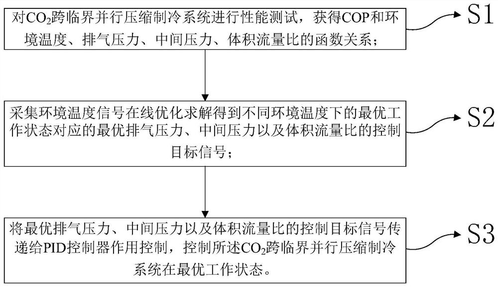
[0074] see figure 2 As shown, the present invention also provides a CO described in Example 1 2 Control methods for transcritical parallel compression refrigeration systems. The present invention a kind of CO 2 The optimal working state of the transcritical parallel compression refrigeration system is the inlet pressure of the gas cooler 12, which is the discharge pressure, the suction pressure of the auxiliary compressor 21, which is the intermediate pressure, and the volume of the auxiliary compressor 21 when the refrigeration COP is the highest when the system is running stably. The ratio of the flow rate and the volumetric flow rate of the main compressor 11 is the volumetric flow ratio; the optimal working state is obtained through the following steps:


PUM


Abstract

The invention discloses a control method of a CO2 transcritical parallel compression refrigeration system. The system comprises a main path transcritical CO2 circulation device and a branch path near-critical CO2 circulation device. The main path transcritical CO2 circulation device comprises a main compressor, a gas cooler, a heat regenerator, a main path throttle valve, an evaporator and a gas-liquid separator which are circularly connected in sequence; a gas outlet of the gas-liquid separator is connected with a gas suction port of the main compressor; the branch path near-critical CO2 circulation device comprises a branch path throttle valve and an auxiliary compressor; and an outlet bypass path of the heat regenerator is connected with the gas suction port of the main compressor through the branch path throttle valve, the heat regenerator and the auxiliary compressor. According to the system, the optimization problem of the optimal exhaust pressure, the optimal intermediate pressure and the optimal volume flow ratio of a parallel compression system can be solved, and the problem that the system deviates from the working condition point with the optimal performance due to the change of the environment temperature in the actual operation process can be solved.

Description

【Technical field】 [0001] The invention belongs to the technical field of refrigeration and low temperature, in particular to a CO 2 Transcritical parallel compression refrigeration system and control method. 【Background technique】 [0002] With social development and scientific and technological progress, heat pump air conditioners have played an important role in people's production and life. Traditional CFCs, HCFCs, and HFCs refrigerants are widely used in the field of refrigeration and air conditioning because of their excellent thermodynamic properties, but the ODP and GWP of Freon refrigerants are high, making it a major development trend to replace Freon refrigerants with natural working fluids . [0003] CO 2 It has excellent heat transfer performance, is non-flammable, and non-toxic. The air-conditioning cycle works in a high-pressure area and has a low specific volume, which can reduce the volume of the equipment. In recent years, transcritical CO 2 The cycle h...

Claims


Application Information

Patent Timeline
IPC IPC(8): F25B9/00F25B31/00F25B40/06F25B41/385F25B49/02G05B11/42G06F30/28G06N3/10G06F119/08
CPCF25B9/008F25B40/06F25B31/00F25B41/385F25B49/02G06F30/28G05B11/42G06N3/10G06F2119/08Y02B30/70
Inventor 曹锋张腾宋昱龙
Owner XI AN JIAOTONG UNIV
Features
  • R&D
  • Intellectual Property
  • Life Sciences
  • Materials
  • Tech Scout
  • Unparalleled Data Quality
  • Higher Quality Content
  • 60% Fewer Hallucinations
Learn More