
Dyeing machine for chemical fiber textiles

A chemical fiber and printing and dyeing machine technology, which is applied in textiles and papermaking, textile material processing, and textile material carrier processing. It can solve the problems of difficult cloth dyeing, increase the cost of printing and dyeing machine manufacturing and use, and the size and weight of the dyeing box. , to achieve the effect of increasing the winding speed, improving the drying effect and reducing the labor intensity

Pending Publication Date: 2021-09-21
孙冶
View PDF5 Cites 0 Cited by
  • Summary
  • Abstract
  • Description
  • Claims
  • Application Information

AI Technical Summary

Problems solved by technology

[0004] The existing printing and dyeing machines for environmentally friendly chemical fiber textiles that remove wrinkles have the following shortcomings: when replacing the dyeing solution, the combination of the adjustment component and the dyeing pool component is used, and the slide plate is used to drive the dyeing box to move and realize the rapid position replacement of the dyeing box. Use a complex structure to replace the dyeing box. Due to the large size and weight of the dyeing box, it not only increases the manufacturing and use costs of the printing and dyeing machine, but also needs to stop dyeing for a short time when replacing the dyeing box, so it is also difficult to apply to large Batch Fabric Dyeing

Method used

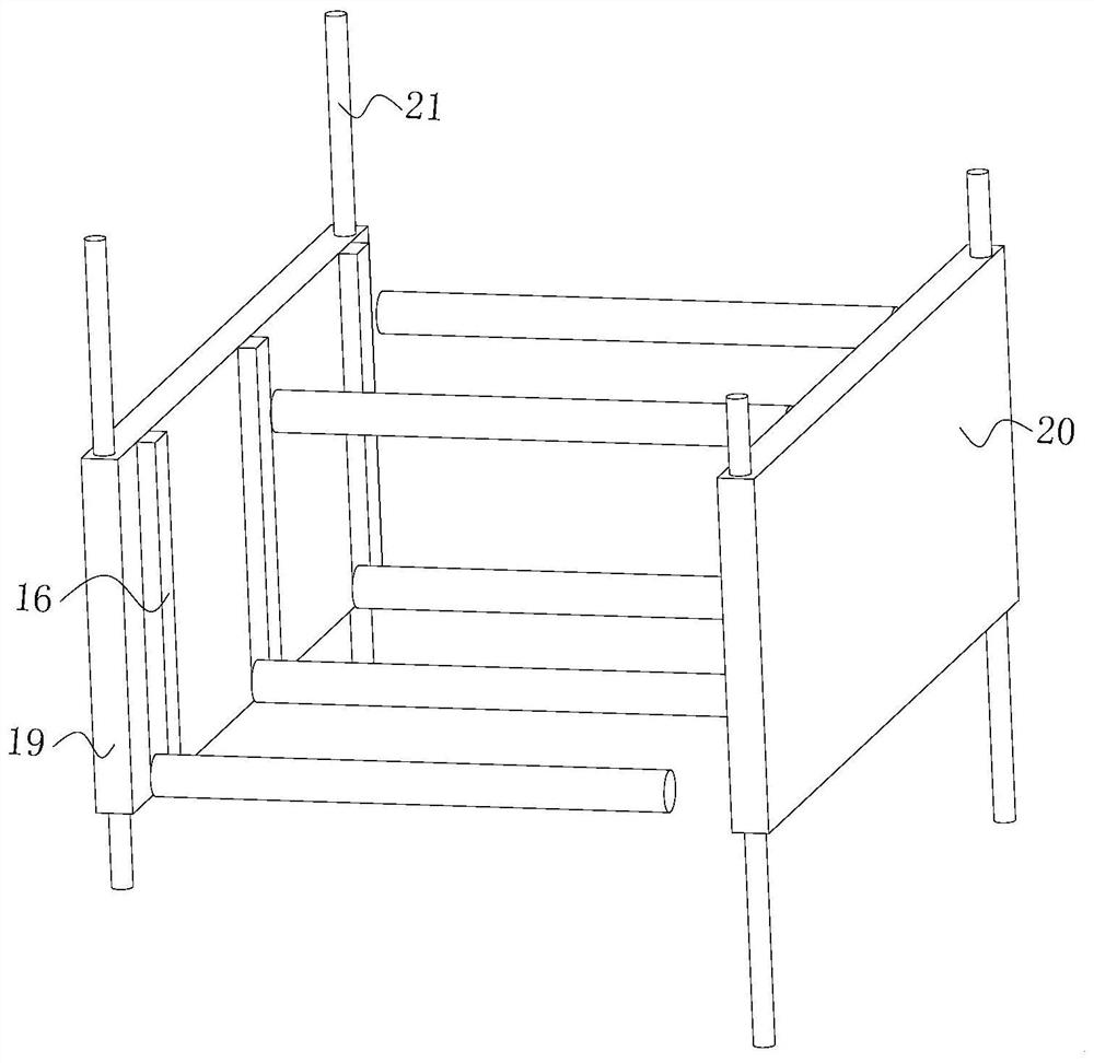
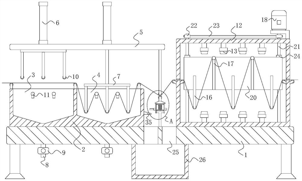
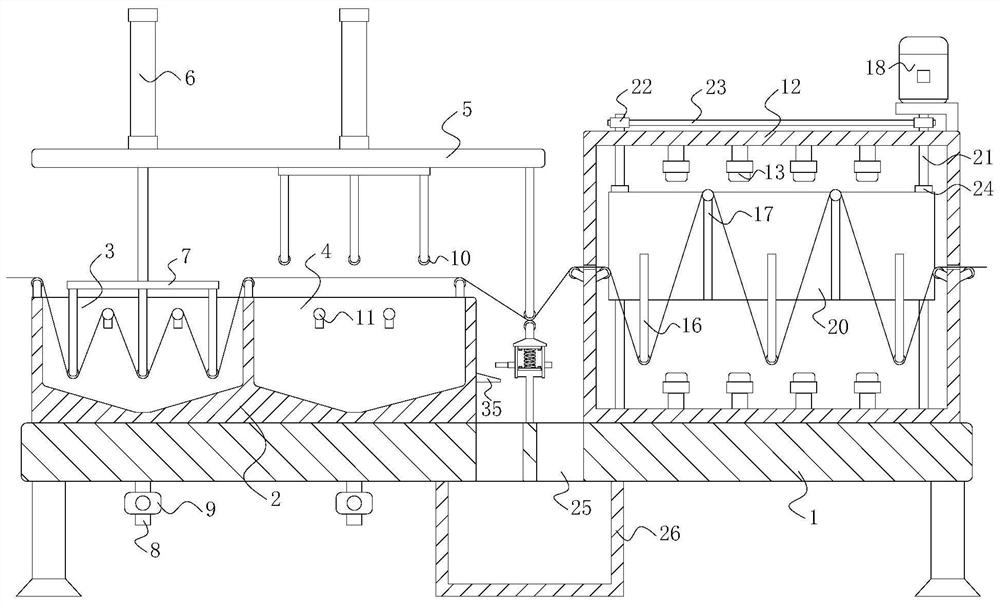

Image

  • Dyeing machine for chemical fiber textiles
  • Dyeing machine for chemical fiber textiles
  • Dyeing machine for chemical fiber textiles

Examples


Embodiment approach

[0045] As an embodiment of the present invention, refer to figure 2 and Figure 8 , the squeeze assembly includes a top roller 27 fixedly mounted on the bottom of the top plate 5, and the top roller 27 is located between the dyeing box 2 and the oven 12, a mounting frame 28 is installed on the top wall of the frame 1, and the top of the mounting frame 28 is provided with Mounting seat 29, the top of mounting seat 29 is rotatably installed with the bottom roller 30 that cooperates with top roller 27, is connected with spring 31 between mounting frame 28 and mounting seat 29, is threaded with spring 31 on the bottom wall of mounting seat 29 The annular cover 32 that cooperates with each other, and the bottom end of the annular cover 32 is sleeved on the outside of the mounting frame 28 can prevent the spring 31 from directly contacting the dyeing solution and getting rusty. The elastically deformable spring 31 can be easily replaced, and the annular cover 32 is provided with a...


PUM


Abstract

The invention relates to the technical field of textile equipment, in particular to a dyeing machine for chemical fiber textiles. The dyeing machine comprises a textile fabric and a dyeing machine body matched with the textile fabric, the dyeing machine body comprises a machine frame, a dyeing box is fixedly mounted on the top wall of one end of the machine frame, and a first dyeing tank and a second dyeing tank which are mutually independent are arranged in the dyeing box; and a top plate is mounted at the top end of the machine frame, two air cylinders are symmetrically mounted at the top wall of the top plate, mounting plates are fixedly connected with the output ends of the two air cylinders, and the two mounting plates are correspondingly located on the upper sides of the first dyeing tank and the second dyeing tank. Dyeing liquid in the dyeing tanks can be replaced by alternately pressing the textile fabric into the first dyeing tank and the second dyeing tank, the structure is simple, operation is convenient, the manufacturing and using cost of the dyeing machine is reduced, and the processing rate of the dyeing machine is remarkably increased due to the fact that the dyeing process does not need to be stopped when the dyeing liquid is replaced, so that the dyeing machine for the chemical fiber textiles is suitable for large-batch cloth dyeing.

Description

technical field [0001] The invention relates to the technical field of textile equipment, in particular to a printing and dyeing machine for chemical fiber textiles. Background technique [0002] Printing and dyeing is also called dyeing and finishing. It is to stick the material with luster to the surface of the cloth, so that the color is attached to the surface of the cloth to achieve the purpose of dyeing. The existing printing and dyeing equipment is to immerse the cloth into the dyeing solution, through However, when the existing printing and dyeing machines are dyeing, only one dyeing vat is installed, and when the dyeing liquid is replaced, it is necessary to stop dyeing and replace the dyeing liquid, resulting in a decrease in the dyeing efficiency of the cloth, which is inconvenient for mass production. Fabric dyed. [0003] After retrieval, Chinese Patent No. CN110846836B discloses a wrinkle-removing environmentally friendly chemical fiber textile printing and dy...

Claims


Application Information

Patent Timeline
Patent Type & Authority Applications(China)
IPC IPC(8): D06B3/12D06B23/04D06B15/02D06B15/00F26B13/08F26B13/14F26B23/04F26B25/20
CPCD06B3/12D06B23/04D06B15/02D06B15/00F26B13/08F26B13/14F26B23/04F26B25/20
Inventor 孙冶钱子岑
Owner 孙冶
Learn More