Air-core coil sensing complementary device, pincerlike multimeter and preparation method of pincerlike multimeter

A multimeter and coil technology, applied in the direction of transformer/inductor coil/winding/connection, inductor, multi-tester circuit, etc., can solve the problems of complicated manufacturing process, different signal size of integrator circuit, weak induction potential, etc. Achieve the effect of meeting the production process requirements, improving position difference defects, and increasing voltage strength

Active Publication Date: 2021-09-24
UNI TREND TECH (CHINA) CO LTD
View PDF13 Cites 0 Cited by
  • Summary
  • Abstract
  • Description
  • Claims
  • Application Information

AI Technical Summary

Problems solved by technology

[0003] 1) The air-core coil is made of enameled wire wound flat on the hollow tube. The manufacturing process is simple and the cost is low; but the disadvantage is that there is a difference in the measurement position, and the indicator needs to guide the customer's use tips by adding the error of the accessory
[0004] 2) Rogowski coil, the first process is to wind the enameled wire evenly on the insulated wire tube, the second process is to wind the shielding layer, the third process is to wrap and fix the transparent tape, the fourth process is to add fiber tape to wrap, and the fifth process is to pack Seal a soft jacket to make a closed loop coil; the manufacturing process is complicated, the cost is too high (more than 10 times that of the air core coil), and the structure is not suitable for the pull-type clamp meter product
[0005] 3) Han's coil, in the first process, the enameled wire is made into multiple monomer air-core windings, in the second process, the mixed colloids such as soft magnetic powder and polymer are used to solidify the monomer windings, and in the third process, multiple identical The windings are connected, the fourth process is through the connection of the flexible PCB, and the fifth process encapsulates the soft jacket to form a closed loop coil; the manufacturing process is complicated, the cost is too high (5 times that of the Rogowski coil), and the structure is not Suitable for clamp meter products
[0008] see Figure 4 , for the traditional air-core coil sensing complementary device, when the alternating current passes through the winding coil, it will present a magnetic force line that changes with time around it, and the changing magnetic force line will generate an induced potential at both ends of the winding coil, so The magnitude of the induced potential will vary with the distance between the current conductor and the winding coil; according to the sensing principle of the inductance coil, when the current conductor is close to the winding coil, the magnitude of the induced potential is the strongest, and vice versa when the distance is long The potential is weak; the calibration points of all current clamp meter products are centered on the axis (such as Figure 4 Area A) is used as the basic data for calibration, while area B is adjusted through VR1 of the adder input circuit to adjust the balance of the left and right input signals entering the integrator, but the top C area and bottom C area of ​​the clamp head cannot be calibrated Yes, the magnetic circuit leakage of the cutting surface of this kind of device, the voltage signal sensed by the second time is the weakest, resulting in the signal transmitted to the integrator circuit with different magnitudes, so the measurement position difference cannot be avoided

Method used


Image

  • Air-core coil sensing complementary device, pincerlike multimeter and preparation method of pincerlike multimeter
  • Air-core coil sensing complementary device, pincerlike multimeter and preparation method of pincerlike multimeter
  • Air-core coil sensing complementary device, pincerlike multimeter and preparation method of pincerlike multimeter

Examples


Embodiment

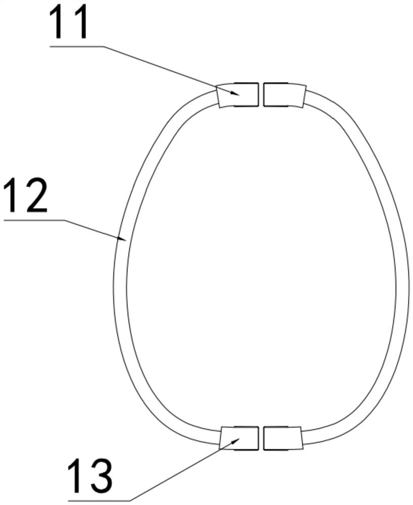
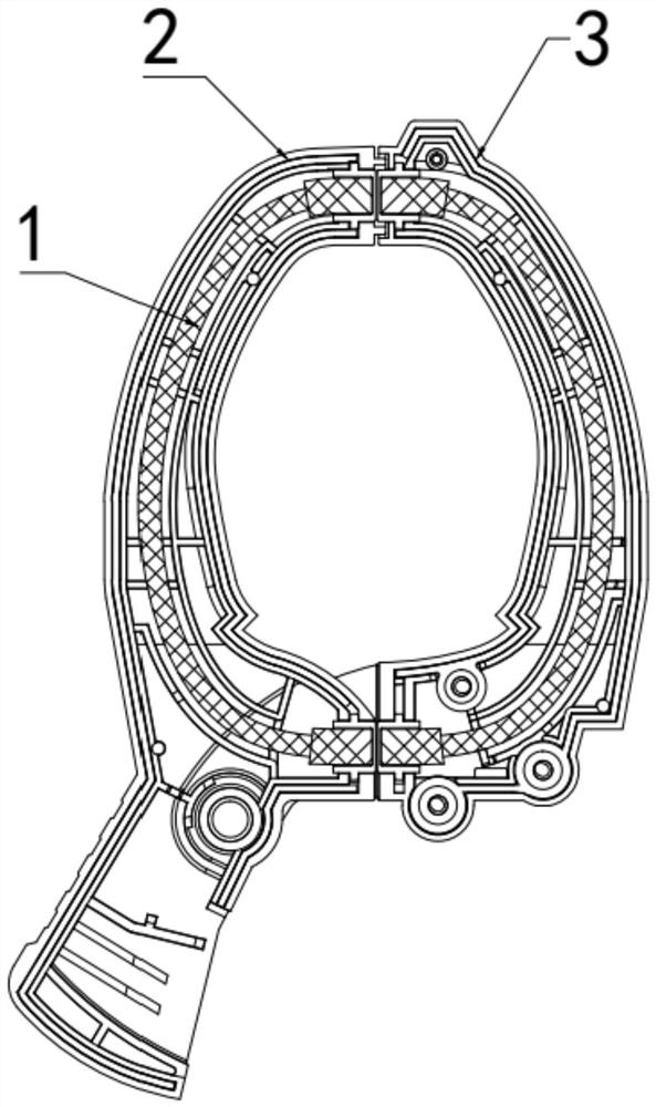
[0041] Example: see figure 1 , an air core coil sensing complementary device provided in this embodiment, which includes two sets of parallel winding coils, the winding coils include a special-shaped hollow frame 1 and an air core wound on the special-shaped hollow frame 1 Coil;

[0042] The special-shaped hollow skeleton 1 includes an integrally formed first thickened skeleton part 11, an intermediate skeleton 12, and a second thickened skeleton part 13. The first thickened skeleton part 11 and the second thickened skeleton part 13 The cross-sectional diameters are all larger than the cross-sectional diameter of the intermediate skeleton 12; specifically, the special-shaped hollow skeleton 1 is a plastic skeleton to prevent magnetic saturation;

[0043] The air-core coil includes a first section, a second section, and a third section respectively extended and formed according to the shapes of the first skeleton thickened part 11, the middle skeleton 12, and the second skele...


PUM

PropertyMeasurementUnit
lengthaaaaaaaaaa
diameteraaaaaaaaaa

Abstract

The invention discloses an air-core coil sensing complementary device which comprises two groups of winding coils connected in parallel, and each winding coil comprises a special-shaped air-core framework and an air-core coil; each special-shaped hollow framework comprises a first framework thickened part, a middle framework and a second framework thickened part, and the section diameter of the first framework thickened part and the section diameter of the second framework thickened part are both larger than the section diameter of the middle framework. Each air core coil comprises a first interval, a second interval and a third interval, and sensing current signals of the first interval and the third interval are larger than sensing current signals of the second interval; and the invention also discloses a pincerlike multimeter with the air core coil sensing complementary device and a preparation method of the pincerlike multimeter. The structures of the two ends of the special-shaped hollow-core framework are improved, designed and thickened, then the hollow-core coil with the corresponding structure is obtained, the voltage intensity of mutual inductance signals of the two ends is improved, and the defect that the hollow-core coil has a magnetic leakage section opening due to the magnetic conduction effect without an iron core so large position errors exist at all positions inside during actual measurement can be solved.

Description

technical field [0001] The invention relates to the technical field of clamp multimeters, in particular to an air-core coil sensing complementary device, a clamp multimeter and a preparation method thereof. Background technique [0002] Since the air-core coil does not contain magnetic saturation components, it has no magnetism, that is, there is no core loss, and the inductance value is not affected by the flowing current, so its response frequency bandwidth is higher than that of traditional transformers with iron cores (generally 0.1Hz-1MHz), and the curve of mutual inductance in the magnetic field is linear, with low distortion and no saturation. Based on this, in recent years, air-core coils, Rogowski coils, Hans coils, etc. have been introduced into measuring instrument products, and different types of coils have different advantages and disadvantages: [0003] 1) The air core coil is made of enameled wire wound flat on the hollow core tube. The manufacturing process ...

Claims


Application Information

Patent Timeline
Patent Type & Authority Applications(China)
IPC IPC(8): H01F27/28H01F27/30H01F38/00G01R15/12
CPCH01F27/28H01F27/306H01F38/00G01R15/12
Inventor 薛运林黄雕薛淦文杨志凌
Owner UNI TREND TECH (CHINA) CO LTD
Why Eureka
Try Eureka