X-ray bulb tube cathode electron enhancement device
An intensifying device and X-ray technology, which is applied in the field of X-ray tubes, can solve the problems of reducing filament life, breakdown, and rapid evaporation of tungsten metal, and achieve the effects of prolonging life, avoiding switching, and reducing the burden of electron emission
- Summary
- Abstract
- Description
- Claims
- Application Information
AI Technical Summary
Problems solved by technology
Method used
Image
Examples
Embodiment 1
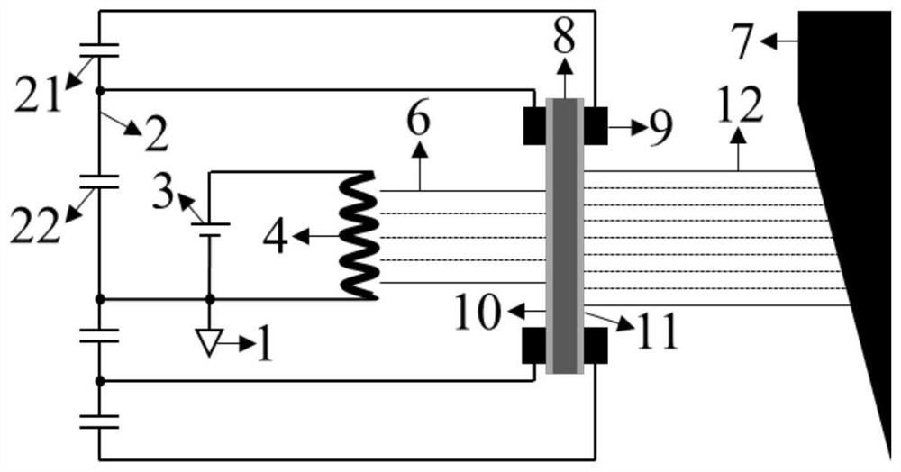
[0029] like figure 1 As shown, the X-ray tube cathode electron enhancement device of this embodiment includes a grounding terminal 1, an AC power supply 3, a cathode 4, and an anode 7. The grounding terminal 1 is a -70kV high-voltage ground, and the AC power supply 3 is a 5-12V low-voltage power supply. , one end of the AC power supply 3 is connected to the ground terminal 1 , both ends of the cathode 4 are connected to the AC power supply 3 , and the anode 7 is arranged opposite to the cathode 4 . The film window 8 is arranged between the cathode 4 and the anode 7, and the two sides of the film window 8 are provided with electrode pairs 9, and the electrode pairs 9 are powered by the capacitor pair 2, and the film window 8, the electrode pair 9, and the capacitor pair 2 form a secondary electron emission source. The capacitor pair 2 includes two capacitors connected in series, namely a first capacitor 21 and a second capacitor 22 , and one end of the second capacitor 22 is ...
Embodiment 2
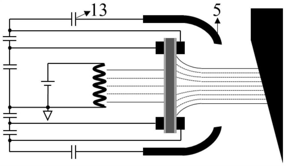
[0035] like figure 2 As shown, the basic composition of the X-ray tube cathode electron enhancement device of this embodiment is the same as that of Embodiment 1, the difference is that this embodiment also includes a grid 5 and a grid capacitor 13, and the grid 5 is arranged on the thin film window 8 On both sides, the gate 5 is connected to a gate capacitor 13 which is connected to a first capacitor 21 . In this embodiment, the grid 5 does not need to have the function of quickly "switching" and "cutting off" X-ray emission, but only needs to realize the control of the focus size and position of the secondary electron beam 12 . The electric field intensity required for the focus control of the secondary electron beam 12 is far lower than the dielectric strength of vacuum, and no electrical breakdown will occur between the grid 5 and the film window 8. Therefore, the voltage of the grid 5 does not need to be very high. The grid 5 also does not need to be placed very close t...
Embodiment 3
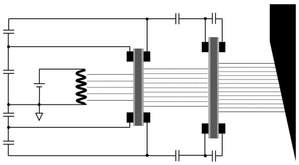
[0039] like image 3 As shown, the basic composition of the X-ray tube cathode electron intensifier device of this embodiment is the same as that of Embodiment 1, except that the secondary electron emission source composed of film window 8, electrode pair 9 and capacitor pair 2 in this embodiment Step-by-step multiplication is set, and the second end of the capacitance pair of the secondary electron emission source of the subsequent stage is connected to the first end of the capacitance pair of the secondary electron emission source of the previous stage. In this embodiment, the electrons emitted from the cathode 4 are accelerated and multiplied step by step and then bombard the anode 7 to emit X-rays. The multi-level electron-enhanced cascaded cathode structure can further reduce the electron emission burden of the filament and better extend the life of the filament.
PUM
 Abstract
Description
Claims
Application Information
 - R&D
- Intellectual Property
- Life Sciences
- Materials
- Tech Scout
- Unparalleled Data Quality
- Higher Quality Content
- 60% Fewer Hallucinations
Browse by: Latest US Patents, China's latest patents, Technical Efficacy Thesaurus, Application Domain, Technology Topic, Popular Technical Reports.
© 2025 PatSnap. All rights reserved.Legal|Privacy policy|Modern Slavery Act Transparency Statement|Sitemap|About US| Contact US: help@patsnap.com


