Flue gas denitration device

A denitrification and flue gas technology, applied in the field of flue gas denitrification treatment, can solve the problems of high catalytic efficiency, flue gas temperature fluctuation range, and inability to ensure catalyst in real time, and achieve stable and reliable work and strong denitrification catalytic ability

Active Publication Date: 2021-09-28
CHONGQING UNIV
View PDF20 Cites 0 Cited by
  • Summary
  • Abstract
  • Description
  • Claims
  • Application Information

AI Technical Summary

Problems solved by technology

[0004] The purpose of the present invention is to provide a flue gas denitrification device for the above shortcomings, and to solve the dependence of the catalyst removal effect of the current denitrification technology on the flue gas temperature. The fluctuation range of the flue gas temperature is large, and it is impossible to ensure the high catalytic efficiency of the catalyst in real time. And other issues

Method used


Image

  • Flue gas denitration device
  • Flue gas denitration device
  • Flue gas denitration device

Examples


Embodiment 1

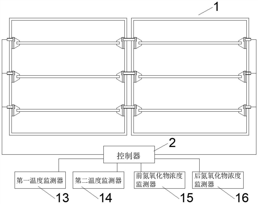
[0024] See attached Figure 1~4 . The flue gas denitration device includes a denitrification catalytic component 1, a monitoring component and a controller 2; the denitrification catalytic component 1 and the monitoring component are electrically connected to the controller 2 respectively; the denitrification catalytic component 1 is used to catalyze nitrogen oxidation in the flue gas The monitoring component is used to monitor the catalytic environment and / or catalytic capacity of the denitrification catalytic component 1, and transmits the monitoring information to the controller 2; the controller 2 is used to control the temperature of the denitrification catalytic component 1 according to the monitoring information . It can be seen from the above structure that this flue gas denitrification device is installed in the SCR reactor; when the temperature of the flue gas at the tail of the boiler is low, the flue gas flowing through the denitrification catalytic component 1 ca...

Embodiment 2

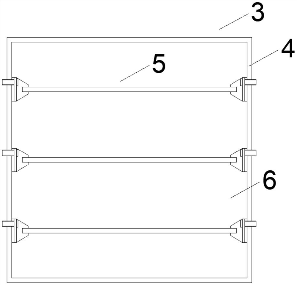
[0026] See attached Figure 1~4 . On the basis of Embodiment 1, the denitration catalytic assembly 1 includes at least one denitration catalytic unit 3; the denitration catalytic unit 3 includes a casing 4 and several catalytic mesh assemblies 5; the casing 4 is surrounded by a catalytic flue 6 ; The catalytic flue 6 is provided with a number of catalytic mesh components 5 . It can be seen from the above structure that the shell 4 is surrounded by a catalytic flue 6, so when the flue gas passes through the denitrification catalytic unit 3, it flows through the determined catalytic flue 6, and the catalytic flue 6 is provided with several catalytic mesh assemblies 5 for the flue gas. Catalytic denitrification of gas.

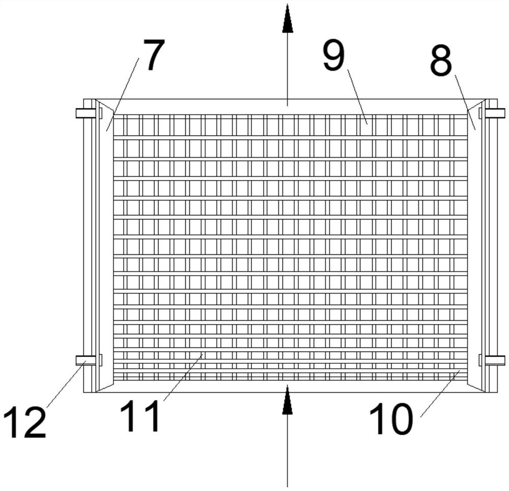
[0027] The catalytic grid assembly 5 includes a left conductive rail 7, a right conductive rail 8 and an electric heating grid 9; the left and right conductive rails 9 of the electric heating grid 9 are respectively connected to the left conductive rail 7 and t...

Embodiment 3

[0029] See attached Figure 1~4 . On the basis of Embodiment 2, the electric heating network 9 includes several electric heating wires 10 and several heat conducting wires 11 with insulating sheaths; several electric heating wires 10 are parallel to each other; several heat conducting wires 11 are parallel to each other; The left end of the heating wire 10 is connected to the left conductive rail 7, and the right end is connected to the right conductive rail 8, and intersects with all the heating wires 11; several heating wires 10 and several heating wires 11 form a network together. It can be seen from the above structure that the left end of each heating wire 10 is connected to the left conductive rail 7, and the right end is connected to the right conductive rail 8. Each heating wire 10 is a path, so even if one heating wire 10 breaks down, it will not affect the entire heating wire 10. The electric heating network 9 is energized to generate heat, which is different from c...


PUM


Abstract

The invention discloses a flue gas denitration device, belonging to the field of flue gas denitration treatment. The flue gas denitration device comprises a denitration catalysis assembly, a monitoring assembly and a controller, wherein the denitration catalysis assembly and the monitoring assembly are electrically connected with the controller; the denitration catalysis assembly is used for catalyzing the reaction of nitrogen oxides in flue gas; the monitoring assembly is used for monitoring the catalytic environment and/or catalytic capability of the denitration catalysis assembly and transmitting monitoring information to the controller; and the controller is used for controlling the temperature of the denitration catalysis assembly according to the monitoring information. According to the flue gas denitration device, the problem that the catalyst removal effect of a current denitration technology depends on a flue gas temperature is solved, catalytic efficiency can be monitored in real time, efficient catalytic efficiency can be kept all the time, and efficient and stable operation of a denitration system can be achieved when a coal-fired power plant participates in power grid deep peak regulation and boiler tail flue gas changes in a large range; and the device is stable and reliable in work and high in denitration catalytic capacity.

Description

technical field [0001] The invention belongs to the field of flue gas denitrification treatment, in particular to a flue gas denitrification device. Background technique [0002] In the past ten years, the problem of air pollution has become one of the social problems that the general public is most concerned about, seriously restricting the healthy development of my country's economy and society. Smog and ozone are the most common air pollution phenomena, and nitrogen oxides are one of the main precursors that cause the above pollution phenomena. However, the total amount of nitrogen oxide emissions is still at a high level, and its further reduction faces a series of difficulties. [0003] Among the existing nitrogen oxide control technologies, the selective catalytic reduction SCR technology using ammonia as the reducing agent is the most mature and efficient, so it is widely used in flue gas denitrification. my country has a complete range of industries, involving a la...

Claims


Application Information

Patent Timeline
Patent Type & Authority Applications(China)
IPC IPC(8): B01D53/86B01D53/56
CPCB01D53/8631B01D2258/0283B01D2255/20723B01D2255/20707B01D2255/20776
Inventor 杜学森李为陶亚琴李志薛宗国杨仲卿冉景煜蒲舸
Owner CHONGQING UNIV
Why Eureka
Try Eureka