Stirring device for fully stirring catalyst and degraded plastic organisms

A technology for degrading plastics and stirring devices, which is applied to mixers with rotating stirring devices, mixer accessories, dissolution, etc. It can solve the problems of reducing stirring efficiency, insufficient grinding, and increasing stirring time, so as to improve stirring sufficient rate and increase Stirring efficiency and the effect of reducing stirring time

Inactive Publication Date: 2021-10-01
杭州麦铺网络科技有限公司
View PDF0 Cites 0 Cited by
  • Summary
  • Abstract
  • Description
  • Claims
  • Application Information

AI Technical Summary

Problems solved by technology

[0005] Aiming at the deficiencies of the prior art, the present invention provides a stirring device for fully stirring the catalyst and degrading plastic organisms. The stirring device can be contracted, which is convenient for putting the bioplastics into the bottom of the stirring box in the early stage, and fully grinds the catalyst. The advantage of fully stirring the catalyst with bioplastics solves the problem that the existing photocatalytic degradation device cannot realize the uniform mixing of plastics and catalysts, and at the same time, as the catalyst is ground and used, its dose is reduced, and the grinding devices on both sides are fixed, which may Insufficient grinding in the middle of use, insufficient catalyst grinding, resulting in reduced catalyst utilization and reduced catalytic efficiency
The position of the stirring roller is fixed, which will cause bioplastics to accumulate on the top of the stirring device for a long time when they are put in, which increases the stirring time and reduces the stirring efficiency.

Method used


Image

  • Stirring device for fully stirring catalyst and degraded plastic organisms
  • Stirring device for fully stirring catalyst and degraded plastic organisms
  • Stirring device for fully stirring catalyst and degraded plastic organisms

Examples


Embodiment 1

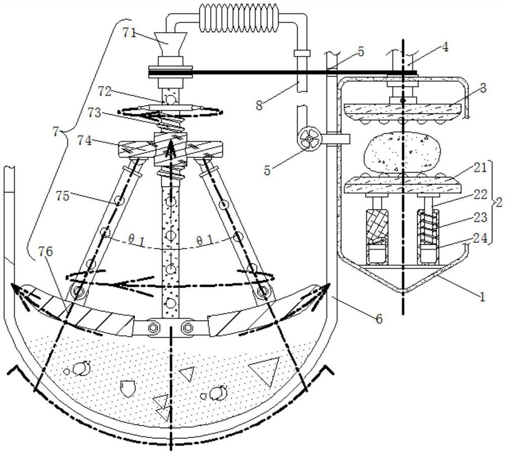
[0025] see Figure 1-2 , a stirring device for fully stirring catalysts and biodegradable plastics, comprising a grinding box 1, an upper grinding disc 3 is installed movable inside the grinding box 1, a rotating shaft 4 is fixedly installed in the middle of the upper grinding disc 3, and the left side of the grinding box 1 A fan 5 is fixedly installed on the side, a stirring box 6 is fixedly installed on the left side of the grinding box 1, and a feeding port is arranged on the left side of the stirring box 6 . A pipeline 8 is installed above the fan 5 .

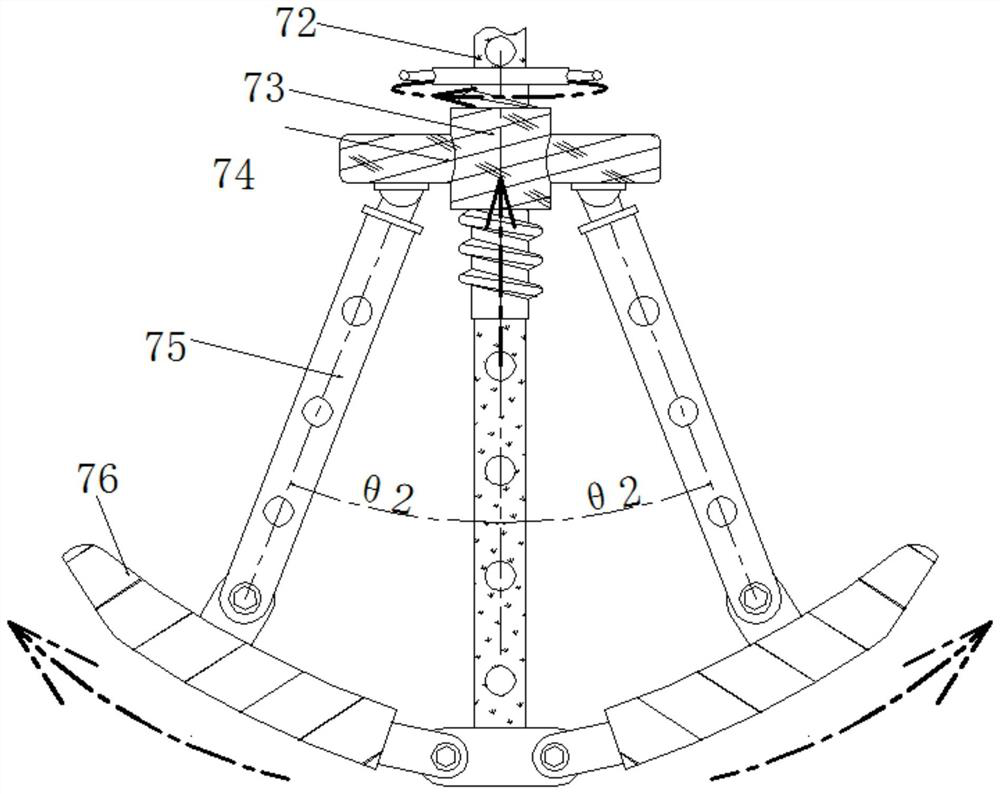
[0026] Including a stirring mechanism 7, a funnel 71 is installed on the top of the stirring mechanism 7, a main rod 72 is installed on the bottom of the funnel 71, a threaded rod 73 is installed on the top of the main rod 72, and a connecting block 74 is threaded in the middle of the threaded rod 73 , Both sides of the connection block 74 are movably equipped with struts 75, and the front and rear sides of the strut 75 ar...

Embodiment 2

[0028] see figure 1 , 3 , a stirring device for fully stirring catalysts and biodegradable plastics, comprising a grinding box 1, an upper grinding disc 3 is installed movable inside the grinding box 1, a rotating shaft 4 is fixedly installed in the middle of the upper grinding disc 3, and the left side of the grinding box 1 A fan 5 is fixedly installed on the side, a stirring box 6 is fixedly installed on the left side of the grinding box 1, and a feeding port is arranged on the left side of the stirring box 6 . A pipeline 8 is installed above the fan 5 .

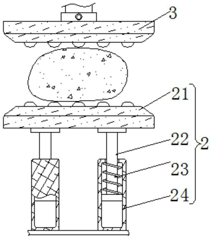
[0029] The middle part of the grinding box 1 is movably equipped with a grinding device 2, a lower grinding disc 21 is arranged above the grinding device 2, and a piston rod 22 is fixedly installed below the lower grinding disc 21, and a spring 23 is sleeved on the outside of the piston rod 22, and the piston rod The below of 22 is fixedly equipped with cylinder 24. The bottom of the piston rod 22 is installed inside th...

Embodiment 3

[0031] see Figure 1-3 , a stirring device for fully stirring catalysts and biodegradable plastics, including a stirring mechanism 7, a funnel 71 is movable above the stirring mechanism 7, a main rod 72 is movable below the funnel 71, and a screw thread is movable above the main rod 72 Rod 73, the middle part of threaded rod 73 is threadedly connected with connection block 74, and the both sides of connection block 74 are movably equipped with support rod 75, and the front and rear sides of support rod 75 evenly offer air-draining hole. The side of the pipe 8 away from the fan 5 is set above the funnel 71, the middle part of the main rod 72 is a hollow structure, and the front and rear sides are uniformly provided with air-draining holes, and the side of the funnel 71 away from the pipe 8 is sleeved on the top of the pole 75 Hollow position in the middle. A support rod 76 is movably installed on the side of the pole 75 away from the connecting block 74 . Support bar 76 is hi...


PUM


Abstract

The invention relates to the technical field of bio-based materials, and discloses a stirring device for fully stirring a catalyst and degraded plastic organisms. The stirring device comprises a stirring mechanism, a funnel is movably mounted above the stirring mechanism, and a main rod is movably mounted below the funnel. By using the catalyst of a lower grinding disc, the weight is reduced, the gravity is reduced, the elastic force of a spring pushes a piston rod to move upwards in an air cylinder and drives the lower grinding disc and the catalyst to move upwards. Friction force between an upper grinding disc and the lower grinding disc is kept, the fineness of the catalyst is improved, and then powder of the catalyst falls into the periphery of a stirring box through vent holes by means of wind power of a fan. The sufficient stirring rate between the catalyst and the biological plastic is improved. A threaded rod rotates to drive a connecting block to move upwards, so that a support shaft pulls a supporting rod to be folded. At the moment, the stirring mechanism is shrunk, the bioplastics are prevented from being stacked above the stirring mechanism when being fed, the stirring time is shortened, and the stirring efficiency is improved.

Description

technical field [0001] The invention relates to the technical field of bio-based materials, in particular to a stirring device for fully stirring catalysts and degrading plastic organisms. Background technique [0002] Bio-based materials refer to biopolymer materials or monomers obtained from renewable raw materials through biotransformation, and then further polymerized to form polymer materials. Bio-based materials include bio-based platform compounds, bioplastics, etc. [0003] After a large number of bioplastics are produced, it is necessary to accelerate the decomposition rate of this type of garbage. After the bioplastics are crushed, catalysts are evenly added to them, and photocatalysis, a non-polluting catalytic approach, is used to accelerate the decomposition rate of bioplastics. The existing photocatalytic degradation device cannot achieve uniform mixing of plastics and catalysts, and at the same time, with the grinding and use of the catalyst, the dosage is de...

Claims


Application Information

Patent Timeline
Patent Type & Authority Applications(China)
IPC IPC(8): B01F13/10B01F7/16B01F15/00B01F15/02B02C7/08
CPCB02C7/08
Inventor 宋兴华
Owner 杭州麦铺网络科技有限公司
Why Eureka
Try Eureka