Rotary kiln low-nitrogen combustion device and production method

A low-nitrogen combustion and low-nitrogen burner technology, applied in rotary drum furnaces, waste heat treatment, furnaces, etc., can solve the problems of low-nitrogen combustion in rotary kilns not reaching the ideal target, single low-nitrogen combustion, etc. The effect of reducing emissions, increasing CO2 concentration

Inactive Publication Date: 2021-10-01
NORTHEASTERN UNIV
View PDF5 Cites 2 Cited by
  • Summary
  • Abstract
  • Description
  • Claims
  • Application Information

AI Technical Summary

Problems solved by technology

[0008] In view of the above-mentioned shortcomings and deficiencies of the prior art, the present invention provides a rotary kiln low-nitrogen combustion device and production method, which solves the problem of using a single low-nitrogen combustion technology and extensive management when the existing cement is calcined to make the rotary kiln low-nitrogen combustion. Technical issues that fall short of ideal goals

Method used


Image

  • Rotary kiln low-nitrogen combustion device and production method
  • Rotary kiln low-nitrogen combustion device and production method
  • Rotary kiln low-nitrogen combustion device and production method

Examples


Embodiment 1

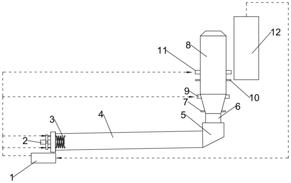
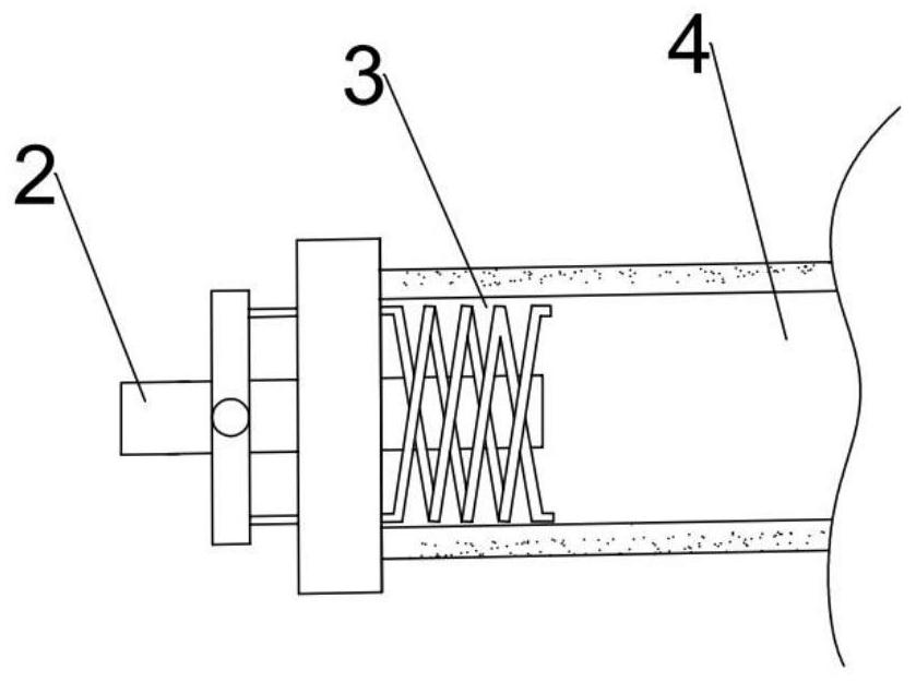
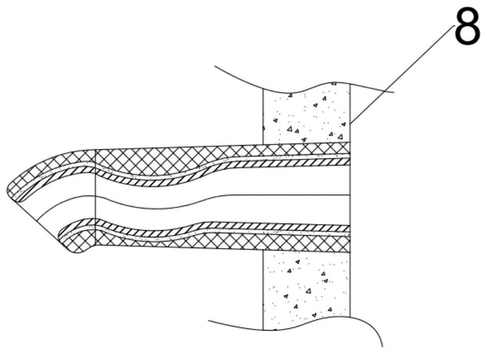
[0040] The present invention proposes a rotary kiln low-nitrogen combustion device for the first time, as shown in Figure 1-3, including a cooler 1, a low-nitrogen burner 2, a secondary air pipe 3, a rotary kiln 4, a decomposition furnace 8 and a preheater 12 . The angle between the rotary kiln 4 and the horizontal plane is 1-3°. Both the low-nitrogen burner 2 and the cooler 1 are arranged at the kiln head of the rotary kiln 4 , and the kiln tail smoke chamber 5 is provided at the kiln tail of the rotary kiln 4 . The calciner 8 includes a conical lower furnace body and an upper furnace body, and the kiln tail smoke chamber 5 is connected to the lower furnace body of the calciner 8 through an ascending flue 6 . The lower part of the lower furnace body of the calciner 8 is provided with two lower coal feeding devices 7, and the upper part is provided with two lower tertiary air ducts 9, and the two lower coal feeding devices are symmetrically distributed on both sides of the ca...

Embodiment 2

[0047] This embodiment proposes a production method based on a rotary kiln low-nitrogen combustion device, the method adopts the rotary kiln low-nitrogen combustion device recorded in the present invention, and includes the following steps:

[0048] S1: Coal powder and primary air are sprayed into the rotary kiln through the low-nitrogen burner, and the high-temperature flue gas in the rotary kiln enters the preheater through the kiln tail flue chamber, ascending flue and calciner in sequence from the kiln tail. The lower primary air volume enables pulverized coal to achieve low-oxygen combustion and inhibits the formation of NOx.

[0049] S2: Pulverized coal is fed from the upper coal feeding device and the lower coal feeding device, and the amount of pulverized coal fed into the lower coal feeding device accounts for 10%-30% of the total amount of pulverized coal fed into the lower coal feeding device and the upper coal feeding device %. The raw meal is fed into the calcine...


PUM


Abstract

The invention relates to a rotary kiln low-nitrogen combustion device and a production method. The rotary kiln low-nitrogen combustion device comprises a cooler, a low-nitrogen combustor, a secondary air pipe, a rotary kiln, a decomposing furnace and a preheater, the lower furnace body of the decomposing furnace is provided with a lower coal feeding device and a lower tertiary air pipe, and the middle lower part of the upper furnace body is provided with an upper coal feeding device and an upper tertiary air pipe; a feeding hole of the preheater communicates with the decomposing furnace, an air outlet of the preheater communicates with an air inlet of the cooler, and an air outlet of the cooler respectively communicates with the secondary air pipe, the lower tertiary air pipe and the upper tertiary air pipe; a spiral ventilation channel is formed in the secondary air pipe; and one end of the secondary air pipe enters the rotary kiln from the kiln head of the rotary kiln and is tightly attached to the kiln wall. The preheater, the cooler, the rotary kiln and the decomposing furnace are used as a whole, the low-nitrogen combustor, staged combustion and O2 / CO2 combustion technologies are combined, generation of NOx in the rotary kiln and the decomposing furnace is controlled at the same time, reduction of existing NOx is enhanced, NOx in the whole process is controlled, and the emission amount of NOx is greatly reduced.

Description

technical field [0001] The invention relates to the field of energy saving and emission reduction of a rotary kiln, in particular to a low-nitrogen combustion device and a production method of a rotary kiln. Background technique [0002] Since 1985, my country's cement production has been ranked first in the world. In 2020, my country's cement production will reach 2.37 billion tons. Cement output is increasing, but cement production is a process with high energy consumption and high pollution. At present, the cement industry has directly caught up with the thermal power generation and transportation industries to become the third largest source of NOx emissions in my country. During the calcination process of cement, due to the high calcination temperature in the kiln, the relative concentration of high temperature in the calcination zone, and the pyrolysis of raw materials, etc., a large amount of NOx will be produced, and many high-concentration metal oxides will be prod...

Claims


Application Information

Patent Timeline
Patent Type & Authority Applications(China)
IPC IPC(8): F27B7/34F27B7/36F27D17/00
CPCF27B7/34F27B7/362F27D17/004F27B2007/365
Inventor 何艳王连勇王睿
Owner NORTHEASTERN UNIV
Why Eureka
Try Eureka