
Intravascular stent

A technology of vascular stents and connectors, applied in the field of biomedical engineering, can solve problems such as separation of stent rings, uneven distribution of radial support force, re-injury of the inner wall of blood vessels, etc., and achieve uniformity, good fatigue resistance, and good adaptability Effects of Vascular Anatomy

Pending Publication Date: 2021-10-08
SHANGHAI INNOCARDIAC MEDICAL TECH CO LTD
View PDF0 Cites 0 Cited by
  • Summary
  • Abstract
  • Description
  • Claims
  • Application Information

AI Technical Summary

Problems solved by technology

[0006] 2. The apex of the stent at both ends of the bare stent may compress the inner wall of the blood vessel, increasing the risk of intimal rupture
[0007] 3. The shortening rate of the stent is large, that is, the length of the tubular stent in its axial direction is easy to decrease
However, the silk nodes are easy to slide on the pole of the bracket. When the node slides from the peaks and valleys to the middle of the pole, the bracket will not only be shortened as a whole, but also its shape will change unpredictablely, which will affect the performance of the overall bracket.
[0008] 4. The bending performance of some bare stents is poor
At the same time, after some existing bare stents have large bends, the small bends will be folded inward, and the cross-sectional area will become smaller, resulting in that the outer surface of the stent cannot fit the inner wall of the blood vessel well.
[0009] 5. At present, there are few vascular stents specially used for the treatment of Debakey type II, especially for Debakey type II, which does not require branch vessel reconstruction and does not involve the aortic arch in dissection
If a traditional covered stent is used for interventional treatment, the polymer film will block the blood supply of the branches of the aortic arch, so it is necessary to make holes in the film and complete the precise fit between the holes and the branch vessels, which greatly increases the difficulty of the operation
[0010] 6. The radial support force distribution in the axial direction is uneven in the whole part of the bare stent, that is, the radial support force of the single-ring stent and the connecting body is greatly different
This results in an uneven distribution of radial support forces across the whole stent
The single-ring stent must have sufficient radial support to anchor the whole stent stably in the blood vessel without slipping. Therefore, the pressure generated by the single-ring stent on the inner wall of the blood vessel is much greater than that of the connecting body, and the inner wall of the blood vessel of the patient Very weak, the single-ring stent that generates high pressure is very likely to cause re-injury to the inner wall of the blood vessel
[0011] 7. The mechanical performance specifications of some existing bare stents are relatively single
The size and specification of the cross-section of the wave rod is relatively fixed, and the mechanical properties of the material itself need to be adjusted through a complex process. Therefore, based on the structural design and manufacturing technology of the existing bracket, it is difficult to produce a variety of brackets with different mechanical properties.
[0012] 8. Some existing bare stents are prone to eccentricity and collapse of the stent ring
After the implantation of some existing bare stents, the probability of failures such as separation, fracture, and dislocation of the stent ring is as high as 9.2%. It is caused by the lack of radial support force of the stent and the lack of axial support

Method used

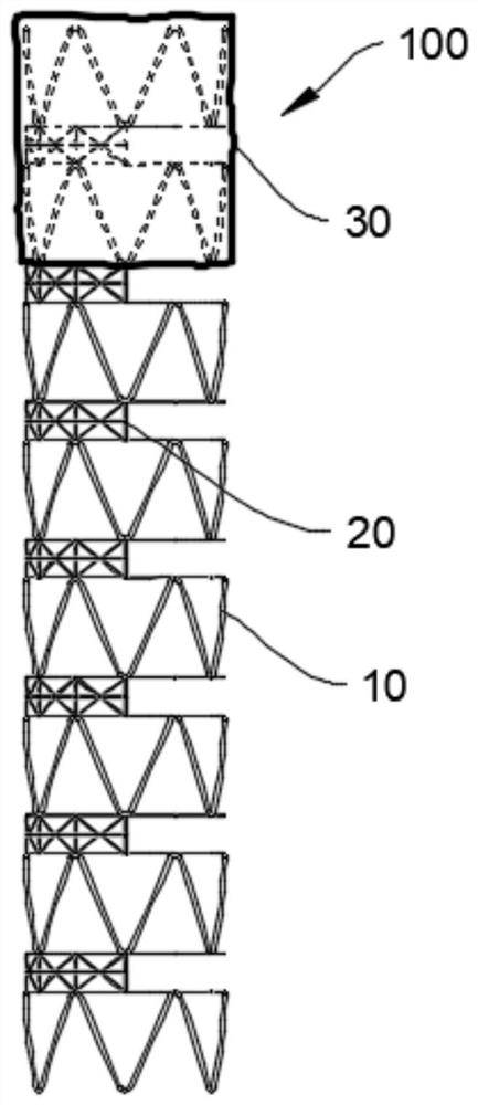
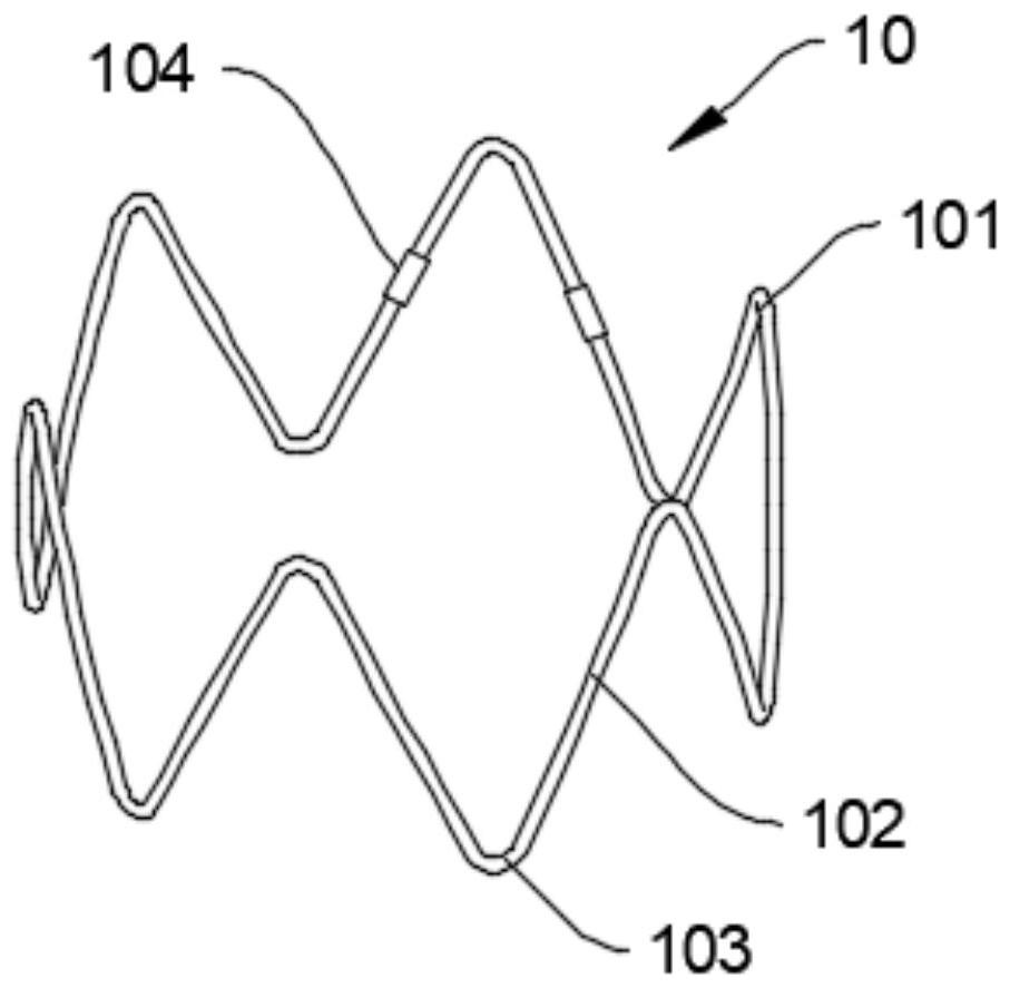
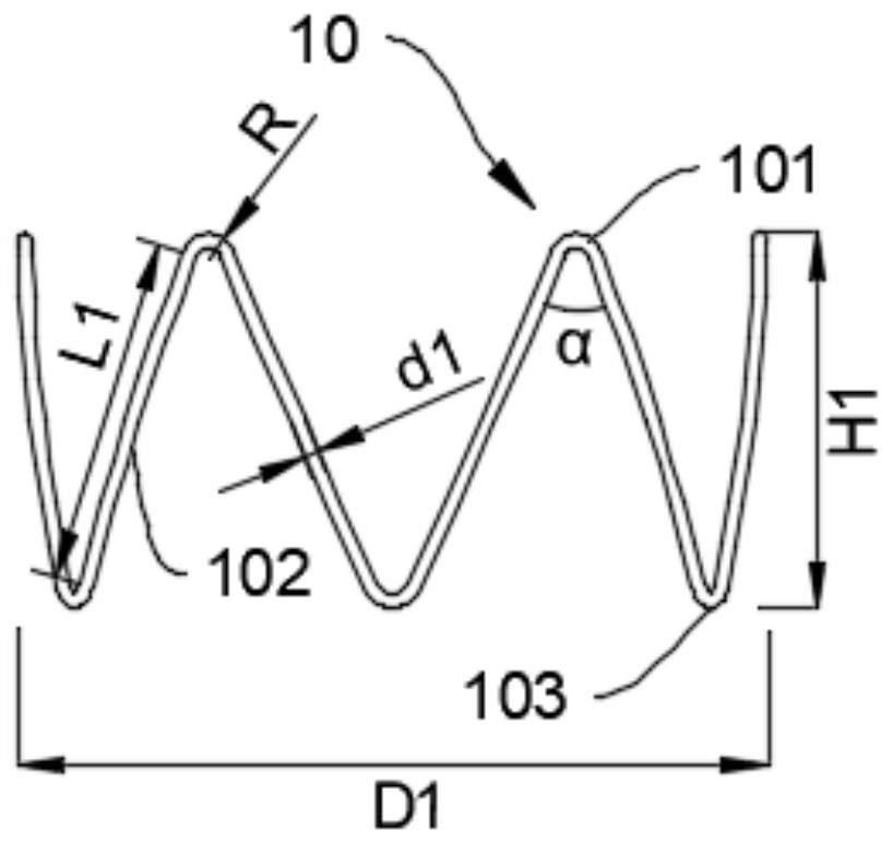

Image

  • Intravascular stent
  • Intravascular stent
  • Intravascular stent

Examples


Embodiment Construction

[0060] Embodiments of the present invention are described below through specific examples, and those skilled in the art can easily understand other advantages and effects of the present invention from the content disclosed in this specification. The present invention can also be implemented or applied through other different specific implementation modes, and various modifications or changes can be made to the details in this specification based on different viewpoints and applications without departing from the spirit of the present invention.

[0061] see Figure 1 - Figure 1 6. It should be noted that the diagrams provided in this embodiment are only schematically illustrating the basic idea of ​​the present invention, and only the components related to the present invention are shown in the diagrams rather than the number, shape and shape of the components in actual implementation. Dimensional drawing, the type, quantity and proportion of each component can be changed arb...


PUM


Abstract

The invention discloses an intravascular stent. The intravascular stent comprises a plurality of single-ring stents, wherein the single-ring stents are arranged at intervals along an axial direction, and the single-ring stents fluctuate in the axial direction to be in a wavy shape while extending in the circumferential direction; and a plurality of connectors, wherein every two adjacent single-ring stents are connected through the corresponding connector; wherein each connector comprises two first circumferential connecting bodies and at least one axial connecting body; one corresponding first circumferential connecting body is connected with a wave crest of one single-ring stent in the circumferential direction, and the other corresponding first circumferential connecting body is connected with a wave trough of another single-ring stent in the circumferential direction; and the axial connecting bodies are connected with the wave crests or the wave troughs or the first circumferential connecting bodies of corresponding two adjacent single-ring stents in the axial direction, and the axial connecting bodies are of non-uniform distribution in the circumferential direction. The intravascular stent disclosed by the invention has different supporting performance and flexibility in the circumferential direction, can better adapt to a blood vessel anatomical structure, and meanwhile, has excellent bending performance and fatigue performance.

Description

technical field [0001] The invention relates to the technical field of biomedical engineering, in particular to a blood vessel stent. Background technique [0002] Thoracic Endovascular Aortic Repair (TEVAR) is a minimally invasive interventional surgery. The femoral artery is percutaneously punctured, and the interventional device such as a covered stent is guided by imaging equipment and delivered along the femoral artery to the Lesion site, a treatment method for local isolation of the dissection site in the vascular cavity. Because it has many advantages such as small trauma, quick recovery, and avoiding some complications of surgery, it is widely used in clinical practice. [0003] The aortic vessel presents a certain taper in its axial direction, the vessel diameter at the proximal end is larger, and the vessel diameter at the distal end is smaller. TEVAR may lead to new stent-induced breaks (Stent-Induced New Entry, SINE ), SINE refers to the fact that the straight ...

Claims


Application Information

Patent Timeline
IPC IPC(8): A61F2/07A61F2/915
CPCA61F2/07A61F2/915A61F2002/91575A61F2002/91591A61F2002/91533A61F2002/91583
Inventor 杨涵曦葛书晨冒鹏志阳明赵益民
Owner SHANGHAI INNOCARDIAC MEDICAL TECH CO LTD
Learn More