Eureka AIR delivers breakthrough ideas for toughest innovation challenges, trusted by R&D personnel around the world.

High-efficiency three-phase separator based on up-flow anaerobic reactor

An upflow anaerobic, three-phase separator technology, which is applied in the field of high-efficiency three-phase separators, can solve the problems of easy sludge loss and insufficient solid-liquid separation effect, so as to improve the treatment effect and ensure the sludge concentration and retention Time, the effect of improving stability

Active Publication Date: 2021-10-22
恩宜瑞(江苏)环境发展有限公司
View PDF6 Cites 0 Cited by
  • Summary
  • Abstract
  • Description
  • Claims
  • Application Information

AI Technical Summary

Problems solved by technology

[0005] In view of the above-mentioned problems, the present invention provides a high-efficiency three-phase separator based on an upflow anaerobic reactor. The reactor has a reasonable structure and can solve the problem of During the operation of the existing upflow anaerobic reactor, the sludge is easy to lose and the solid-liquid separation effect is insufficient, so as to improve the treatment effect of the upflow anaerobic reactor

Method used


Image

  • High-efficiency three-phase separator based on up-flow anaerobic reactor
  • High-efficiency three-phase separator based on up-flow anaerobic reactor
  • High-efficiency three-phase separator based on up-flow anaerobic reactor

Examples


Embodiment

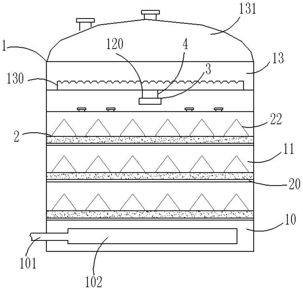
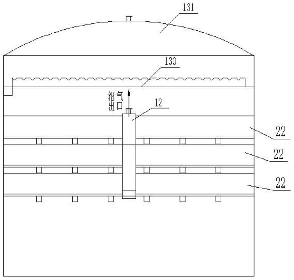
[0041] Such as figure 1 As shown, a high-efficiency three-phase separator based on an upflow anaerobic reactor includes a separation shell 1 that can be divided into a reaction zone 10, a three-phase separation zone 11, and a precipitation zone 13 from bottom to top. The separation element 2 in the three-phase separation area 11, the gas collection chamber 12 communicated with the separation element 2 through a pipeline, and the mud discharge air guide 3 arranged in the gas collection chamber 12;

[0042] The reaction zone 10 is located above the raw water distribution pipe, the side wall of the reaction zone 10 is provided with a liquid inlet, the reaction zone 10 is provided with a sludge reaction bed plate, the sludge fluidized bed plate is provided with an overflow weir, and the gas collection chamber 12 is provided with air outlet 120, and described settling zone 13 is provided with outlet weir 130, and the structure of outlet weir 130 is as follows Figure 11 As shown, ...


PUM

PropertyMeasurementUnit
heightaaaaaaaaaa
heightaaaaaaaaaa

Abstract

The invention provides a high-efficiency three-phase separator based on an up-flow anaerobic reactor. The high-efficiency three-phase separator comprises a separation shell and a separation element, wherein the separation shell can be divided into a reaction area, a three-phase separation area, a gas collection chamber and a settling area from bottom to top; and the separation element is arranged in the three-phase separation area. According to the invention, the sludge loss can be avoided, the sludge precipitation can be accelerated, and the sludge concentration and retention time of the bed layer are ensured, so that the treatment effect of the up-flow anaerobic reactor is improved. By arranging a sufficient number of reflecting covers, firstly, a gas-liquid mixture is separated from sludge particles, and the flow state of rising liquid is shaped into an ordered plug flow mode in the device, so that the sludge can be sufficiently and quickly precipitated. In addition, the height of the gas collection chamber has enough allowance, and the upper part is provided with a defoaming piece, so that a stable gas-liquid interface is formed to realize efficient separation and collection of gas. In a word, the three-phase separator is reasonable in design, the treatment efficiency of the up-flow anaerobic reactor can be remarkably improved, and the three-phase separator has a good application prospect.

Description

technical field [0001] The invention belongs to the technical field of wastewater anaerobic treatment, in particular to a high-efficiency three-phase separator based on an upflow anaerobic reactor. Background technique [0002] Anaerobic biological treatment technology is a process in which facultative anaerobic and anaerobic microbial populations convert organic matter into methane and carbon dioxide under anaerobic conditions. Since the treatment process does not require oxygen supply, it can reduce a large amount of system energy consumption, and has the advantages of good COD removal effect, high reaction rate and strong adaptability to toxic substances, so anaerobic reaction is widely used in the water treatment industry. [0003] At present, the most widely used process device is the upflow anaerobic sludge reactor (UASB). Its working principle is to enter the sewage from the bottom of the reactor and pass through the anaerobic sludge bed from bottom to top. Anaerobic...

Claims


Application Information

Patent Timeline
Patent Type & Authority Applications(China)
IPC IPC(8): C02F3/28
CPCC02F3/28C02F2203/006Y02E50/30
Inventor 李晓陈振郭志成徐敬生吕路
Owner 恩宜瑞(江苏)环境发展有限公司
Why Eureka
Eureka Blog
Learn More