Solid secondary battery and method for manufacturing same

A technology of secondary batteries and manufacturing methods, applied in the field of machines, products or compositions, and processes, capable of solving problems such as liquid leakage, high cost, and fire

Pending Publication Date: 2021-10-22
SEMICON ENERGY LAB CO LTD
View PDF3 Cites 0 Cited by
  • Summary
  • Abstract
  • Description
  • Claims
  • Application Information

AI Technical Summary

Problems solved by technology

However, secondary batteries using liquids have the following problems: due to the use of liquids, electrolyte decomposition reactions and liquid leakage to the outside of the secondary battery occur due to the use of temperature ranges or use potentials.
In addition, secondary batteries using liquid as an electrolyte have a risk of fire due to liquid leakage
[0006] As a secondary battery that does not use a liquid, there is a fuel cell, but it is a device that uses a noble metal as an electrode and the material of a solid electrolyte is also expensive

Method used


Image

  • Solid secondary battery and method for manufacturing same
  • Solid secondary battery and method for manufacturing same
  • Solid secondary battery and method for manufacturing same

Examples


Embodiment approach 1

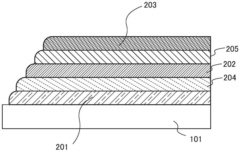
[0058] figure 1 It is one of the embodiments showing the case where the thin-film solid-state secondary battery is a single-layer unit. Note that, in this specification, a single-layer unit of a solid secondary battery refers to a group including at least a positive electrode, a solid electrolyte layer, and a negative electrode.

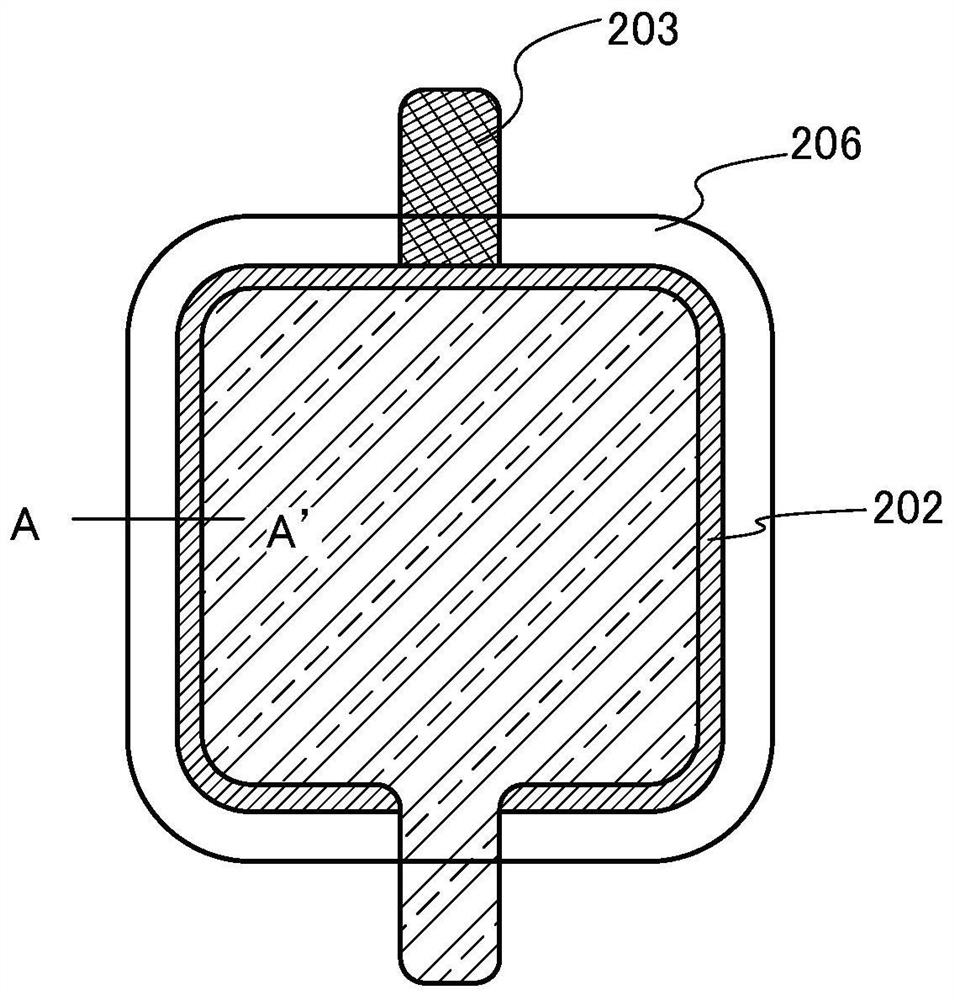
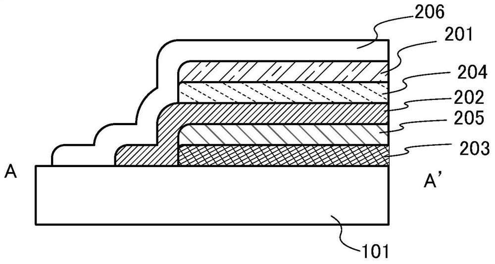
[0059] exist figure 1 In the single-layer unit shown, a positive electrode 201 , a positive electrode active material layer 204 , a solid electrolyte layer 202 , a negative electrode active material layer 205 , and a negative electrode 203 are sequentially stacked on a substrate 101 . Notice, figure 1 The shown cross-sectional view is only a part, and it is arranged so that the planar area of ​​the positive electrode is smaller than that of the negative electrode. In addition, the ends are rounded, at figure 1 Only one of the ends is shown.

[0060] Examples of the substrate 101 include ceramic substrates, glass substrates, plastic substrates, s...

Embodiment approach 2

[0084] An example of a single-layer unit was shown in Embodiment 1, but an example of a multi-layer unit is shown in this embodiment. Figure 4 and Figure 5 It is one of the embodiments showing the case where the thin-film solid-state secondary battery is a multilayer unit.

[0085] Figure 4 An example of a section of a three-story unit is shown.

[0086] A positive electrode 201 is formed on a substrate 101, and a positive electrode active material layer 204, a solid electrolyte layer 202, a negative electrode active material layer 205, and a negative electrode 203 are sequentially formed on the positive electrode 201, thereby constituting the first unit.

[0087] Furthermore, a second negative electrode active material layer, a second solid electrolyte layer, a second positive electrode active material layer, and a second positive electrode are sequentially formed on the negative electrode 203 , thereby constituting the second unit.

[0088] Furthermore, a third layer o...

Embodiment approach 3

[0094] Figure 6A This is an external view of a thin-film solid-state secondary battery. The secondary battery 913 includes a terminal 951 and a terminal 952 . Terminal 951 is electrically connected to the positive pole, and terminal 952 is electrically connected to the negative pole.

[0095] Figure 6B This is the external view of the battery control circuit. Figure 6B The battery control circuit shown includes substrate 900 and layer 916 . A circuit 912 and an antenna 914 are disposed on the substrate 900 . The antenna 914 is electrically connected to the circuit 912 . Terminal 971 and terminal 972 are electrically connected to circuit 912 . The circuit 912 is electrically connected to the terminal 911 .

[0096] The terminal 911 is connected to, for example, a device supplied with power from a thin-film solid state secondary battery. For example, the terminal 911 is connected to a display device, a sensor, and the like.

[0097] The layer 916 has, for example, a ...


PUM

PropertyMeasurementUnit
surface temperatureaaaaaaaaaa
thicknessaaaaaaaaaa
relative permittivityaaaaaaaaaa

Abstract

Provided are: an all-solid secondary battery, specifically a thin-film solid secondary battery, having higher safety than conventional lithium ion secondary batteries that use an electrolytic solution; and a method for manufacturing the same. According to the present invention, a mixed material obtained by codeposition of SiO and a lithium organic complex is used as a solid electrolyte. In other words, a solid electrolyte layer comprising a mixed material of an inorganic material and an organic material is used in a solid secondary battery. The ratio of oxygen to silicon in the solid electrolyte layer is greater than 1 but less than 2.

Description

technical field [0001] One aspect of the present invention relates to an article, a method, or a manufacturing method. Furthermore, one aspect of the present invention relates to a process (process), a machine (machine), a product (manufacture), or a composition (composition of matter). One aspect of the present invention relates to a semiconductor device, a display device, a light emitting device, an electrical storage device, a lighting device, or an electronic device, and a manufacturing method thereof. [0002] In this specification, an electronic device refers to any device having a power storage device, and an electro-optical device having a power storage device, an information terminal device having a power storage device, and the like are all electronic devices. Background technique [0003] In recent years, the development of electronic devices carried by users or electronic devices worn by users has been very active. [0004] An electronic device carried by a use...

Claims


Application Information

Patent Timeline
Patent Type & Authority Applications(China)
IPC IPC(8): H01M4/134H01M4/139H01M4/38H01M10/052H01M10/056H01M10/0562H01M10/0585
CPCH01M10/0562Y02E60/10Y02P70/50H01M4/483H01M4/0426H01M2300/0071H01M10/0525H01M10/0585H01M10/056H01M4/139H01M4/131H01M10/052H01M4/386H01M10/058H01M2004/027H01M2004/028
Inventor 山崎舜平栗城和贵田岛亮太米田祐美子
Owner SEMICON ENERGY LAB CO LTD
Why Eureka
Try Eureka