Impinging stream type ionization high-temperature waste gas harm removal, separation, degradation and circulation treatment device

A high-temperature waste gas, recycling treatment technology, applied in gaseous discharge wastewater treatment, grease/oily substance/float removal device, combined device, etc., can solve the problem of slow filtration speed, air pollution, no harmful gas and solid impurities degradation And separation and other issues, to increase the speed, increase the use time, achieve the effect of eliminating harmful substances and filtering emissions

Active Publication Date: 2021-10-29
徐州众迈节能环保科技有限公司
View PDF3 Cites 3 Cited by
  • Summary
  • Abstract
  • Description
  • Claims
  • Application Information

AI Technical Summary

Problems solved by technology

Boiler combustion generally uses coal as fuel. The exhaust gas generated by coal combustion contains carbon monoxide, nitrogen monoxide, sulfur dioxide, solid dust and other components, and the high-temperature exhaust gas will further generate harmful substances such as dioxin when it contacts the air, and the exhaust gas is directly discharged Air will cause atmospheric pollution. During the treatment of high-temperature waste gas, the heat energy carried by high-temperature waste gas is often not treated, and it is still discharged in the form of high-temperature air, which is more likely to cause thermal pollution to the environment and damage the ecological environment.
[0003] After searching, the Chinese patent application number is CN108079709A, which discloses a high-temperature exhaust gas treatment device, which includes a vertically arranged first pipe body, a horizontally arranged second pipe body, a vertically arranged third pipe body, The fourth pipe body and the fifth pipe body, the upper end of the first pipe body communicates with the upper end of the third pipe body through the second pipe body, one end of the fourth pipe body communicates with the first pipe body, The other end is inclined downward toward the third pipe body; one end of the fifth pipe body communicates with the third pipe body, and the other end is inclined downward toward the first pipe body; The lower end of the pipe body communicates with the lower end of the fifth pipe body, a plurality of nozzles are respectively arranged in the first pipe body, the second pipe body and the third pipe body, and the side wall of the first pipe body is provided with a One end of the air intake pipe communicates with the first pipe body, the other end is provided with an air inlet, and the side wall of the third pipe body is horizontally provided with an air outlet pipe; the purification pipe is vertically arranged At the end of the gas outlet pipeline, one end of the purification pipeline communicates with the top of the end of the gas outlet pipeline, and the other end is provided with a gas outlet and communicates with the outside atmosphere. A purification unit for purifying the exhaust gas is arranged in the purification pipeline. It can recover energy from the waste heat of industrial waste gas, which is energy-saving and environmentally friendly, but it cannot effectively filter industrial waste gas and discharge it without pollution, and when water resources are recycled, it cannot effectively filter water resources before using them
[0004] At present, the existing waste gas treatment devices generally pass the waste gas into the scrubber, and then cool it down and wash it with water, and then discharge it into the atmosphere. However, they cannot effectively degrade and separate the harmful gases and solid impurities contained in the waste gas. The rate is not high. When recycling water resources, the harmful substances contained in the water resources cannot be filtered before use. As a result, when the water resources are sprayed on the waste gas, not only cannot effectively degrade the harmful substances contained in the waste gas, but it is more likely to Increase the content of harmful substances in the exhaust gas, resulting in low efficiency of water resource recycling. It is impossible to quickly filter the fixed impurities, small impurities and tiny impurities contained in the exhaust gas layer by layer. The existing exhaust gas treatment device is filtering the exhaust gas. Only water resources are used to spray the waste gas. This method can cool down the high-temperature waste gas and adsorb the fixed impurities contained in the waste gas. As a result, the temperature of the water resource itself rises gradually, thereby reducing the recycling efficiency of water resources. On the other hand, water spray can adsorb large fixed impurities, but it is difficult to adsorb fine and tiny dust, resulting in exhaust gas passing through When the filter layer is used, the dust blocks the gas filter layer, causing the overall filtration speed of the exhaust gas to slow down. In severe cases, the internal pressure of the exhaust gas treatment device will increase, resulting in damage to the filter device, which greatly affects the filtration and emission of exhaust gas, which cannot meet people's current requirements for exhaust gas. The need for pollution-free emissions

Method used


Image

  • Impinging stream type ionization high-temperature waste gas harm removal, separation, degradation and circulation treatment device
  • Impinging stream type ionization high-temperature waste gas harm removal, separation, degradation and circulation treatment device
  • Impinging stream type ionization high-temperature waste gas harm removal, separation, degradation and circulation treatment device

Examples


Embodiment Construction

[0026] The technical solution of this patent will be described in further detail below in conjunction with the specific implementation. The technical features or connection relationships described in the present invention are not described in detail. They are all existing technologies adopted.

[0027] The present invention will be described in further detail below in conjunction with the accompanying drawings.

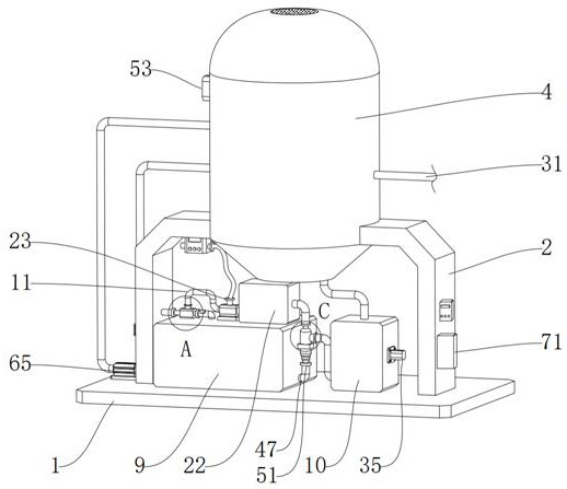
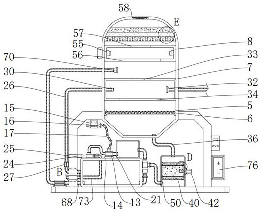
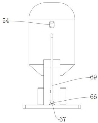
[0028] Such as figure 1 , figure 2 , image 3 , Figure 4 with Figure 5 As shown, the present invention provides an impinging flow ionization high-temperature waste gas detoxification separation and degradation cycle treatment device, including a separation bottom support base 1, a separation tower support frame 2, a collision type negative pressure separation and degradation tower 4, an inertial impact Flow mixing periodic swing box 7, adsorption electrostatic state dust cleaning storage box 8, multi-functional integrated waste gas degradation water storage tan...


PUM


Abstract

The invention discloses an impinging stream type ionization high-temperature waste gas harm removal, separation, degradation and circulation treatment device. The device comprises a separation bottom supporting seat, a separation tower supporting frame, a clash type negative pressure separation and degradation tower, an inertia type impinging stream mixing periodic swinging box, an adsorption type electrostatic state dust cleaning and storage box, a multifunctional integrated waste gas degradation water storage box, an ultrasonic waste water circulation purification and harm removal box, an impinging stream waste gas atomization cooling adsorption and degradation mechanism, a circulating cooling waste water ultrasonic purification mixing oil reduction mechanism, an all-dimensional electrostatic adsorption dust storage treatment mechanism, a negative pressure absorption waste gas filtering zero emission mechanism, a spraying covering cooling dust removal cooling mechanism and a temperature difference type power generation heat collection cooling emission mechanism. The invention belongs to the technical field of industrial waste gas treatment, and particularly provides an impinging stream type ionization high-temperature waste gas harm removal, separation, degradation and circulation treatment device which integrates separation and degradation of harmful substances contained in high-temperature waste gas and adsorbs and filters dust in all directions.

Description

technical field [0001] The invention belongs to the technical field of industrial waste gas treatment, and specifically refers to an impinging flow ionization high-temperature waste gas detoxification separation degradation cycle treatment device. Background technique [0002] A large amount of energy is required in industrial production, and boiler combustion is usually required to convert the internal energy into electrical energy output through a series of conversions. Boiler combustion generally uses coal as fuel. The exhaust gas generated by coal combustion contains carbon monoxide, nitrogen monoxide, sulfur dioxide, solid dust and other components, and the high-temperature exhaust gas will further generate harmful substances such as dioxin when it contacts the air, and the exhaust gas is directly discharged Air will cause atmospheric pollution. In the process of high-temperature waste gas treatment, the heat energy carried by high-temperature waste gas is often not tre...

Claims


Application Information

Patent Timeline
Patent Type & Authority Applications(China)
IPC IPC(8): B01D53/32B01D53/26B01D50/00B01D47/06C02F9/02C02F103/18
CPCB01D53/26B01D53/32B01D47/06B01D50/00C02F9/00C02F1/001C02F1/40C02F1/281C02F2103/18
Inventor 李维强
Owner 徐州众迈节能环保科技有限公司
Why Eureka
Try Eureka