Desulfurization and denitrification device
A desulfurization and denitration and pretreatment device technology, applied in the field of desulfurization and denitrification, can solve the problems of insufficient desulfurization and denitrification reaction, slow purification speed of desulfurization device, etc., and achieve the effect of thorough reaction, accelerated reaction speed and increased reaction area
- Summary
- Abstract
- Description
- Claims
- Application Information
AI Technical Summary
Problems solved by technology
Method used
Image

Examples
Embodiment example 1
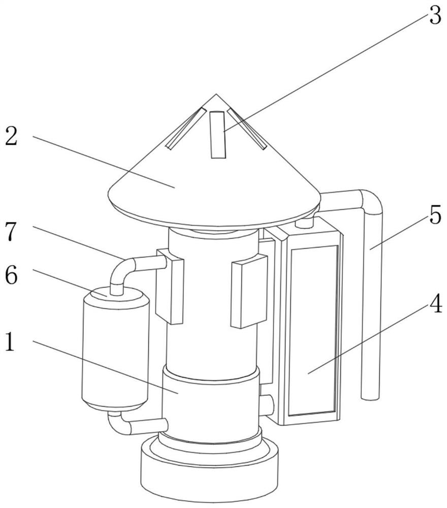
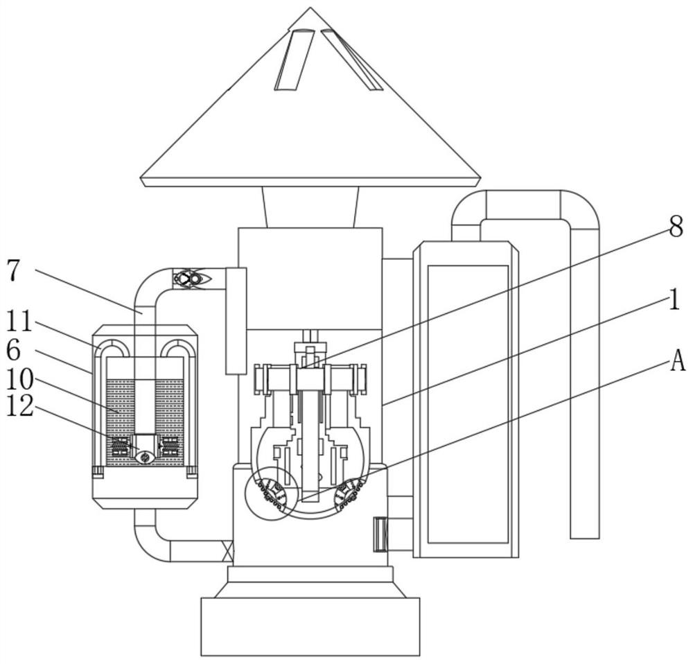
[0027] see Figure 1-3 , the present invention provides a technical solution: a desulfurization and denitrification device, including a reaction tower 1, the top of the reaction tower 1 is provided with an outlet air flow top cover 2, and an outer discharge groove 3 is provided outside the top of the outlet air flow top cover 2, and the reaction tower 1 is right The side is provided with an inlet pretreatment device 4, the top of the inlet pretreatment device 4 is provided with an inlet pipe 5, and the left side of the reaction tower 1 is provided with a reflux reaction tank 6, and the upper and lower ends of the reflux reaction tank 6 are connected to the reaction tower through the air guide pipe 7. 1 connected, a desulfurization and denitrification reaction tank 10 is installed inside the reflux reaction tank 6, and the air guide pipe 7 above the reflux reaction tank 6 extends to the inside of the desulfurization and denitration reaction tank 10, and a part of the unprocessed...
Embodiment example 2
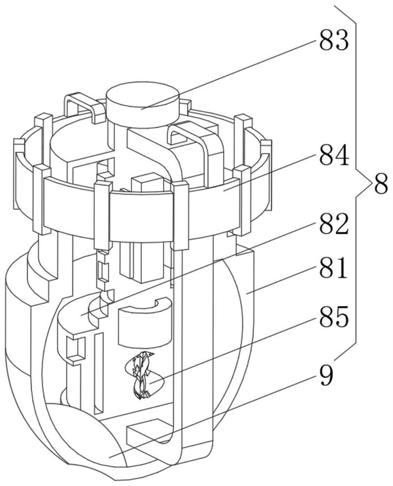
[0032] see Figure 4 , on the basis of the first embodiment, the present invention provides a technical solution: the internal mixing acceleration device 8 includes a hemispherical mixing device 81, an inner bubbling disc 82 is arranged inside the hemispherical mixing device 81, and a center of the inner bubbling disc 82 is provided with Separate the stirrer 85, the top of the hemispherical mixing device 81 is provided with an upper mounting seat 83, the outer ring of the upper mounting seat 83 is provided with an outer ring heating ring 84, and the position between the inner side of the bottom of the hemispherical mixing device 81 and the inner foaming plate 82 is provided with a mixing mechanism 9. The output end of the driving mechanism of the device drives the internal mixing acceleration device 8 to rotate. When the internal internal mixing acceleration device 8 is rotating at a high speed, it cooperates with the internal foaming plate 82 to quickly bubble and speed up the...
Embodiment example 3
[0034] see Figure 5, on the basis of the implementation case 1 and the implementation case 2, the present invention provides a technical solution: the mixing mechanism 9 includes a mechanism body 91, the center of the mechanism body 91 is provided with a central tube 92, and the sides of the mechanism body 91 are provided with inner elastic rings 96, the bottom of the center tube 92 is provided with an outer discharge hole 95, and the center tube 92 is located inside the main body 91 of the mechanism and is provided with an inner inlet hole 94'.
[0035] The middle position inside the central tube 92 and the position corresponding to the inner inlet hole 94 are all provided with a magnetic block 93, and the corresponding side of the magnetic block is set as a magnetic pole of the opposite sex. The central tube 92 is located at the end of the inner inlet hole 94. The magnetic block 93 adopts the corresponding magnetic poles that attract each other, so that the moving central t...
PUM
 Abstract
Description
Claims
Application Information
 - R&D
- Intellectual Property
- Life Sciences
- Materials
- Tech Scout
- Unparalleled Data Quality
- Higher Quality Content
- 60% Fewer Hallucinations
Browse by: Latest US Patents, China's latest patents, Technical Efficacy Thesaurus, Application Domain, Technology Topic, Popular Technical Reports.
© 2025 PatSnap. All rights reserved.Legal|Privacy policy|Modern Slavery Act Transparency Statement|Sitemap|About US| Contact US: help@patsnap.com