Condensation heat recovery heat pump hot water system for sludge drying system

A technology for sludge drying and heat pump hot water, which is applied in heat recovery systems, dewatering/drying/concentrating sludge treatment, fluid heaters, etc. Production and on-site installation, good waste heat recovery effect, and high waste heat utilization rate

Pending Publication Date: 2021-11-05
CEEC HUNAN ELECTRIC POWER DESIGN INST
View PDF0 Cites 1 Cited by
  • Summary
  • Abstract
  • Description
  • Claims
  • Application Information

AI Technical Summary

Problems solved by technology

[0002] At present, with the development of society and economy, the improvement of people's living standards, and the expansion of cities, the amount of sludge generated has also increased. Sludge treatment projects have emerged in various places. At present, the main means of sludge treatment is drying and then incineration or There is a large amount of water vapor in the tail gas exhausted by the sludge dryer, which is a high-temperature and high-humidity gas. A large amount of condensed water will be generated during the transportation process. The generation of condensed water will lead to corrosion of pipelines and leakage of foul-smelling water, causing environmental pollution.
Usually, the measure to avoid the generation of condensed water is to insulate the pipeline for conveying exhaust gas. Although it can reduce the amount of condensed water, it cannot fundamentally solve the generation of condensed water, and the waste heat cannot be utilized, resulting in waste of resources.

Method used


Image

  • Condensation heat recovery heat pump hot water system for sludge drying system

Examples


Embodiment Construction

[0015] The present invention will be described in further detail below in conjunction with the accompanying drawings and specific embodiments.

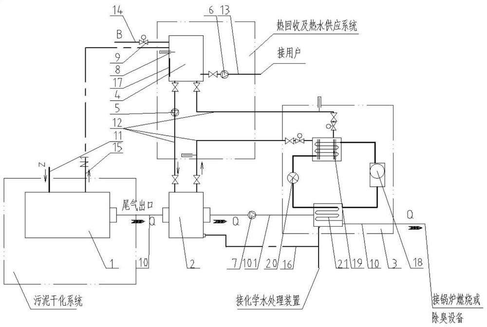
[0016] Such as figure 1 As shown, this embodiment includes a sludge drying system, a condensation heat recovery device, a heat pump water heater unit, a heat recovery and hot water supply system. The sludge drying system includes a sludge drying unit 1, a steam pipe 11, a steam condensate pipe 15 and a first air pipe 10 (for transporting exhaust gas); the heat pump water heater unit 3 is composed of a compressor 18, a condenser 19. Consists of throttle valve 20 and evaporator 21. The heat recovery and hot water supply system includes a hot water tank 4, a heat recovery circulating water pump 5, a hot water supply pump 6, a replenishment valve 9 and a replenishment pipe 14. The hot water tank, the condensation heat recovery device and the condenser 19 of the heat pump hot water unit are connected through the heat recovery circulating ...


PUM


Abstract

The invention provides a condensation heat recovery heat pump hot water system for a sludge drying system. The condensation heat recovery heat pump hot water system comprises the sludge drying system and a heat pump hot water unit, wherein a steam outlet of the sludge drying system is connected with a hot water tank; a tail gas outlet of the sludge drying system is connected with a condensation heat recovery device; the heat pump hot water unit comprises a compressor, a condenser, a throttling valve and an evaporator which are connected in sequence; and the hot water tank, the condensation heat recovery device and the condenser are connected through a pipeline to form a water circulation heating pipeline. Compared with the prior art, the condensation heat recovery heat pump hot water system is simple, easy to produce and mount on site, good in waste heat recovery effect and high in waste heat utilization rate, and has obvious environmental friendliness. By the condensation heat recovery heat pump hot water system, the problem of generation of condensate water in a tail gas conveying process after sludge drying can be effectively solved, and waste heat in a drying process can be effectively recovered.

Description

technical field [0001] The invention relates to a heat recovery system, in particular to a condensation heat recovery heat pump hot water system used in a sludge drying system. Background technique [0002] At present, with the development of society and economy, the improvement of people's living standards, and the expansion of cities, the amount of sludge generated has also increased. Sludge treatment projects have emerged in various places. At present, the main means of sludge treatment is drying and then incineration or There is a large amount of water vapor in the tail gas exhausted by the sludge dryer, which is a high-temperature and high-humidity gas. A large amount of condensed water will be generated during the transportation process. The generation of condensed water will lead to corrosion of pipelines and leakage of foul-smelling water, causing environmental pollution. Usually, the measure to avoid the generation of condensed water is to insulate the pipes conveyi...

Claims


Application Information

Patent Timeline
Patent Type & Authority Applications(China)
IPC IPC(8): F24H4/02F24H9/00F24H9/20C02F11/13
CPCF24H4/02F24H9/0005F24H9/2007C02F11/13Y02B30/52
Inventor 陈贺伟黄双全李学军徐欣
Owner CEEC HUNAN ELECTRIC POWER DESIGN INST
Why Eureka
Try Eureka