Heavy metal pollutant treatment equipment

A technology for pollutant treatment and heavy metal, applied in the field of heavy metal pollution, can solve the problems of cost and harvest not proportional, energy and time, contact neps and other problems, to reduce maintenance time and cost, strengthen the effect, increase the contact area Effect

Inactive Publication Date: 2021-11-16
刘宸玮
View PDF1 Cites 0 Cited by
  • Summary
  • Abstract
  • Description
  • Claims
  • Application Information

AI Technical Summary

Problems solved by technology

[0006] Aiming at the deficiencies of the prior art, the present invention provides a heavy metal pollutant treatment equipment, which solves the problem that the internal contact neps are very small, the reaction efficiency is low, and the energy consumed by the reaction is solved during the self-reaction process of the existing heavy metal pollutant treatment equipment. The time is too long, the cost is not proportional to the harvest, and the problem of wasting resources

Method used


Image

  • Heavy metal pollutant treatment equipment
  • Heavy metal pollutant treatment equipment
  • Heavy metal pollutant treatment equipment

Examples


Embodiment 1

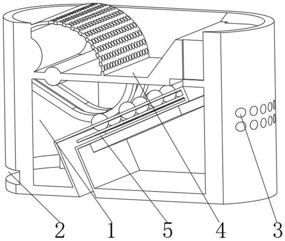
[0038] see Figure 1-3 , the present invention provides a technical solution: a heavy metal pollutant treatment equipment, specifically comprising:

[0039] Processing box 1, the processing box 1 has a loop-back box body, and an outlet 2 provided at the bottom of the left side outer wall of the loop-back box body, and a vent hole 3 provided at the middle position of the right side outer wall of the loop-back box body, and installed in the loop-back box body The primary filter device 4 on the top of the surface, and the reaction device 5 installed at the bottom of the primary filter device 4, balance the internal and external air pressure through the setting of the vent hole 3, so as to avoid the change of the internal and external air pressure caused by the reaction gas generated during the treatment process, which will affect the internal heavy metal pollution The processing process of the material ensures that the processing process is smooth and the reaction is more fully a...

Embodiment 2

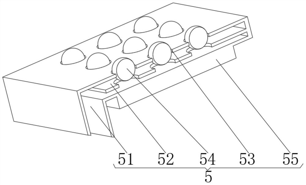
[0049] see Figure 1-5 , on the basis of Embodiment 1, the present invention provides a kind of technical scheme: primary filter device 4 comprises:

[0050] End plate 41, this end plate 41 has semicircle plate body, and the positioning shaft 42 that is installed on the right side of semicircle plate body, and the winder 43 that is installed on the top of semicircle plate body, and the branch that is installed on winder 43 outer surfaces Screen plate 44, and the bearing plate 45 that is installed on the outer surface of the positioning shaft 42, and the flow hole 46 that is opened on the right side of the bearing plate 45, and the inclined plane infusion pump 47 that is installed on the top of the bearing plate 45 and is located above the flow hole 46, and The bent rod device 48 installed on the bottom of the end plate 41 . The design of the inclined plane infusion pump 47 can preliminarily precipitate the heavy metal pollutants, avoiding the blockage of the equipment by the ...


PUM


Abstract

The invention discloses heavy metal pollutant treatment equipment which specifically comprises a treatment box, a discharge port formed in the bottom of the outer wall of the left side of a loopback box body, a vent hole formed in the middle of the outer wall of the right side of the loopback box body, a primary filtering device mounted at the top of the inner surface of the loopback box body, and a reaction device mounted at the bottom of the primary filtering device. The reaction device comprises a guide plate, a cutting device mounted in the middle of an inner cavity of the L-shaped shell, a mounting hole formed in the top of the L-shaped shell, a purification ball mounted on the inner surface of the mounting hole and a pneumatic pump mounted at the bottom of the L-shaped shell, wherein the cutting device is mounted in the middle of the inner cavity of the L-shaped shell. The invention relates to the technical field of heavy metal pollution. Internal and external air pressures are balanced through the vent hole, so that the situation that the internal and external air pressures are changed due to reaction gas generated in the treatment process and the treatment process of internal heavy metal pollutants is affected is avoided, the treatment process is smooth, and the reaction is more sufficient and thorough.

Description

technical field [0001] The invention relates to the technical field of heavy metal pollution, in particular to heavy metal pollution treatment equipment. Background technique [0002] Wastewater containing heavy metal ions mainly comes from industrial wastewater such as mining, nonferrous metals, electroplating, electrolysis, pesticides, medicine, tobacco, paints, and pigments. Heavy metal ions mainly include all heavy metal ions such as copper, lead, zinc, iron, cobalt, nickel, manganese, cadmium, mercury, tungsten, and molybdenum. Because heavy metal ions cannot be decomposed by themselves, they are easy to accumulate in organisms, disrupting the normal metabolic activities of organisms, and causing great harm to humans and the environment. [0003] The patent of Chinese patent CN101088938B discloses a treatment method of heavy metal sewage, adopts electrochemical catalytic oxidation technology, adjusts pH value to neutral sewage, introduces into the reaction tower, fills...

Claims


Application Information

Patent Timeline
Patent Type & Authority Applications(China)
IPC IPC(8): C02F9/04C02F101/20
CPCC02F9/00C02F2101/20C02F1/001C02F1/00C02F1/5281C02F2001/007
Inventor 刘宸玮
Owner 刘宸玮
Why Eureka
Try Eureka