Friction damping device, passive joint with same and surgical robot

A friction damping and joint technology, applied in the field of surgical robots, can solve the problems of permanent magnet brake release, complex structure and circuit, and achieve the effect of easy maintenance and replacement, and easy assembly and maintenance.

Active Publication Date: 2021-11-16
常州唯精医疗机器人有限公司
View PDF7 Cites 0 Cited by
  • Summary
  • Abstract
  • Description
  • Claims
  • Application Information

AI Technical Summary

Problems solved by technology

[0006]The present invention is to solve the existing surgical robot with complex structure and circuit. At this time, if electromagnetic interference or other factors cause the permanent magnet brake to be powered suddenly, it may cause The permanent magnet brake releases the shaft, allowing the shaft to turn freely

Method used


Image

  • Friction damping device, passive joint with same and surgical robot
  • Friction damping device, passive joint with same and surgical robot
  • Friction damping device, passive joint with same and surgical robot

Examples


specific Embodiment approach 1

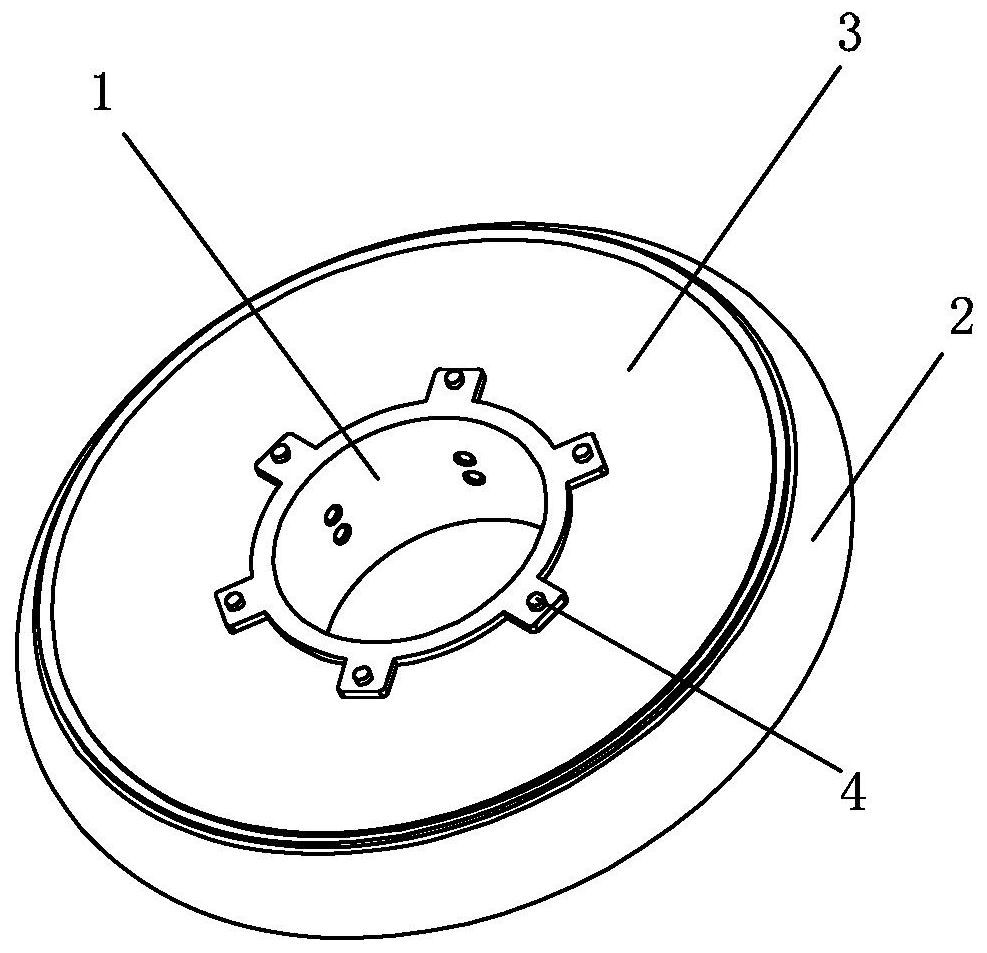
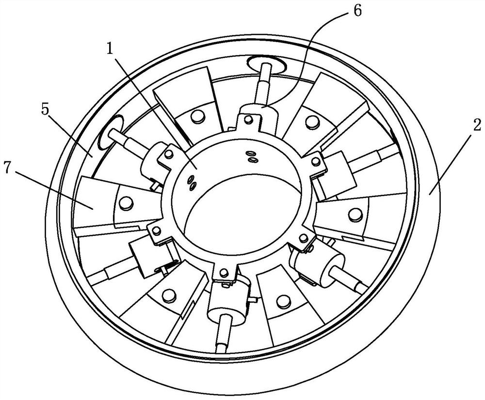
[0035] Specific implementation mode one: combine figure 1 and figure 2 To illustrate this embodiment, a friction damping device described in this embodiment includes a hollow shaft 1, a friction wheel 2, a hub 5, an actuator assembly 6 and a spoke assembly 7;

[0036] The hollow shaft 1 is arranged coaxially with the hub 5, and the hollow shaft 1 is provided with a plurality of spoke assemblies 7 along the outer surface of the circumference, and at least two actuator assemblies 6 are arranged between the plurality of spoke assemblies 7, and each actuator assembly 6. The bottom is fixedly connected with the outer wall of the hollow shaft 1. The hub 5 is provided with the same number of through holes as the actuator assemblies along the circumferential direction, and the top of each actuator assembly 6 is inserted into the through holes of the hub 5. The outer surface of the hub 5 A friction wheel 2 is sheathed on the surface;

[0037]In this specific embodiment, when in use,...

specific Embodiment approach 2

[0038] Specific implementation mode two: combination Figure 5 and Figure 6 Describe this embodiment. This embodiment is a further limitation on the damping device described in the first specific embodiment. In the friction damping device described in this embodiment, the actuator assembly 6 includes a force transmission unit and a force transmission unit. Sensor 6-8; one end of the force transmission unit abuts against the middle of the measuring end face of the force sensor 6-8, and the other end abuts against the friction wheel 2, which is used to transmit the external pressure received by the friction wheel 2 to the force sensor 6-8 to monitor the friction wheel 2 The amount of friction that can be provided;

[0039] In this specific embodiment, such a structure is adopted to improve the stability of the device during rotation.

specific Embodiment approach 3

[0040] Specific implementation mode three: combination Figure 5 Describe this embodiment. This embodiment is a further limitation on the damping device described in the second specific embodiment. In the friction damping device described in this embodiment, the force transmission unit includes a push rod 6-1, an upper Sleeve 6-2, lower sleeve 6-4, spring 6-5 and actuating rod 6-6;

[0041] The lower sleeve 6-4 is provided with an upper sleeve 6-2, and the center of the upper surface of the upper sleeve 6-2 is provided with a dowel bar, and the upper surface of the dowel bar is provided with a circular groove, and the groove The inside of the spring 6-5 is provided with a spring 6-5, and the top of the spring 6-5 is provided with an actuating rod 6-6, and the middle part of the upper surface of the actuating rod 6-6 is provided with a through hole, and the bottom of the push rod 6-1 is inserted as a The inside of the through hole on the upper surface of the moving rod 6-6;

...


PUM


Abstract

The invention discloses a friction damping device, a passive joint with the same and a surgical robot and relates to the technical field of surgical robots. In order to solve the problem that in an existing surgical robot with a complicated structure and circuit, if a permanent magnet brake is suddenly electrified due to electromagnetic interference or other factors, the permanent magnet brake possibly releases a rotating shaft to enable the rotating shaft to rotate freely, and on the other hand, personnel such as operation assistants may touch a mechanical arm to enable the rotating shaft to rotate, so that major personal safety accidents may be caused. A hollow shaft and a hub are coaxially arranged, wherein a plurality of spoke assemblies are evenly arranged on the outer surface of the circumference of the hollow shaft; an actuator cylinder assembly is arranged between every two spoke assemblies, and the bottom of each actuator cylinder assembly is fixedly connected with the outer wall of the hollow shaft through bolts; a plurality of through holes are formed in the outer surface of the circumference of the hub; the top of each actuator cylinder assembly is inserted into one through hole in the outer surface of the hub; and the outer surface of the hub is sleeved with a friction wheel. The friction damping device is suitable for the surgical robot.

Description

technical field [0001] The invention relates to the technical field of surgical robots, in particular to a frictional damping device, a passive joint with the same, and a surgical robot. Background technique [0002] The minimally invasive surgical robot system enables the doctor to observe the tissue characteristics in the patient's body through a two-dimensional or three-dimensional display device at the main console, and to control the robotic arm and surgical tools on the slave robot to complete the operation by remote control. Doctors can complete the operation of minimally invasive surgery in the same way and feeling as traditional surgery, which greatly reduces the difficulty of doctors performing minimally invasive surgery, and also improves the efficiency and safety of surgery, and enables the realization of remote surgery A breakthrough has occurred. It enables the doctor to perform surgery away from the patient, or to perform surgery next to the patient in the wa...

Claims


Application Information

Patent Timeline
Patent Type & Authority Applications(China)
IPC IPC(8): F16D66/02F16D65/02F16D65/14A61B34/35
CPCF16D66/02F16D65/02F16D65/14A61B34/35A61B34/70A61B34/76A61B2034/305F16D2121/20
Inventor 不公告发明人
Owner 常州唯精医疗机器人有限公司
Why Eureka
Try Eureka