
Reversed polarity plasma spraying gun for ultra-low pressure plasma spraying

A plasma, reverse polarity technology, applied in the direction of plasma, climate sustainability, electrical components, etc., can solve the problems of reducing the compression effect of the nozzle, reducing the service life of the electrode, reducing the heating effect of the jet on the powder, etc., to reduce the burning effect. Corrosion effect, prolong service life, increase the effect of residence time

Active Publication Date: 2021-11-19
SICHUAN UNIV
View PDF12 Cites 2 Cited by
  • Summary
  • Abstract
  • Description
  • Claims
  • Application Information

AI Technical Summary

Problems solved by technology

The above two schemes have the following defects: 1) The electrodes of the above two spray guns are rod-shaped cathodes and straight cylindrical anodes, and the traditional positive connection method is adopted with the power supply. This structure has a lower arc voltage (30-50V). The only way to achieve greater power and jet enthalpy is to increase the current, but the increase in current will lead to rapid ablation of the electrode, thereby reducing the service life of the electrode and contaminating the coating, which limits the further promotion and application of the spray gun; 2) spray The outside of the tube is cooled by cooling water, which will quickly take away the heat of the nozzle and keep the inner wall of the nozzle at a lower temperature. The gasified powder will rapidly cool, solidify, and bond, thereby blocking the nozzle and making the spray gun unable to work normally for a long time; 3) The gradually expanding trumpet-shaped nozzle design will reduce the compression effect of the nozzle on the jet to a certain extent, thereby reducing The heating effect of the jet on the powder makes it difficult for the powder to achieve sufficient melting and gasification

Method used


Image

  • Reversed polarity plasma spraying gun for ultra-low pressure plasma spraying

Examples


Embodiment Construction

[0023] The technical solutions in the embodiments of the present invention will be clearly and completely described below in conjunction with the accompanying drawings in the embodiments of the present invention. Obviously, the described embodiments are only some of the embodiments of the present invention, not all of them. Based on the embodiments of the present invention, all other embodiments obtained by persons of ordinary skill in the art without creative work, any modifications, equivalent replacements, improvements, etc., shall be included in the protection scope of the present invention Inside.

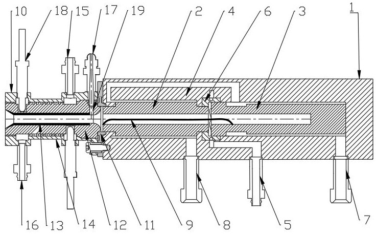
[0024] like figure 1 Shown, a kind of reverse polarity plasma spraying gun that is used for ultra-low pressure plasma spraying of the present invention comprises gun body 1 and external spray pipe 10; Anode 3, insulating body 4, main gas inlet pipe 5, main gas distribution ring 6, cooling water inlet pipe 7 and cooling water outlet pipe 8; the external nozzle 10 includes cera...


PUM


Abstract

The invention discloses a reversed polarity plasma spraying gun for ultralow-pressure plasma spraying. The reversed polarity plasma spraying gun comprises a gun body part and an external spraying pipe part. The gun body part adopts a reversed polarity electrode structure design of a front central through hole cathode and a rear cup-shaped anode, so that the spray gun can realize higher power under the condition of lower current, and the ablation of the electrode and the pollution of the coating are reduced; a graphite spray pipe with a straight-barrel-shaped through hole is adopted as an external spray pipe part, the jet flow temperature under low pressure is increased through compression jet flow, the retention time of powder in a high-temperature jet flow area is greatly prolonged, and the powder can be fully melted and gasified under the conditions of a low-pressure environment and small spray gun power; and the graphite spray pipe is quantitatively cooled by adopting gas cooling, so that the inner wall of the spray pipe is at a higher temperature, and the problem that powder deposits and blocks the inner wall of the pipe wall is effectively solved in combination with larger plasma gas flow.

Description

technical field [0001] The invention relates to the field of plasma spraying, in particular to a reverse polarity plasma spraying gun used for ultra-low pressure plasma spraying. Background technique [0002] Ultra-low pressure plasma spraying is widely used because it can prepare columnar structure thermal barrier coatings similar to electron beam vapor deposition. Compared with traditional atmospheric spray coatings, this coating has better resistance and thermal shock resistance. Applied in key hot-end components of aero-engines that require high coating performance. In the ultra-low pressure (50-200 Pa) environment, the plasma jet ejected from the outlet of the spray gun can be extended to 2 m in length, and the diameter can be increased to 200-400 mm, but because the density of the plasma jet outside the outlet is significantly reduced, it is also The heating ability of the powder by the external plasma jet is greatly reduced, and it is a huge challenge to realize the ...

Claims


Application Information

Patent Timeline
Patent Type & Authority Applications(China)
IPC IPC(8): H05H1/26H05H1/28
CPCH05H1/26H05H1/28Y02T50/60
Inventor 余德平刘方圆邱吉尔尹政鑫姚进
Owner SICHUAN UNIV
Learn More