

Thermal fluid image processing method and system, terminal and medium
An image processing and thermal fluid technology, applied in image data processing, image analysis, instruments, etc., can solve the problems of difficult image identification and segmentation, complex steps, and complex processing procedures, and achieve accurate and reliable processing results, fast processing speed, less sensitive effects
- Summary
- Abstract
- Description
- Claims
- Application Information
AI Technical Summary
Problems solved by technology
Method used
Image

Examples
Embodiment Construction
[0052] The embodiments of the present invention are described in detail below: the present embodiment is implemented under the premise of the technical solution of the present invention, and detailed implementation methods and specific operating procedures are provided. It should be noted that those skilled in the art can make some modifications and improvements without departing from the concept of the present invention, and these all belong to the protection scope of the present invention.
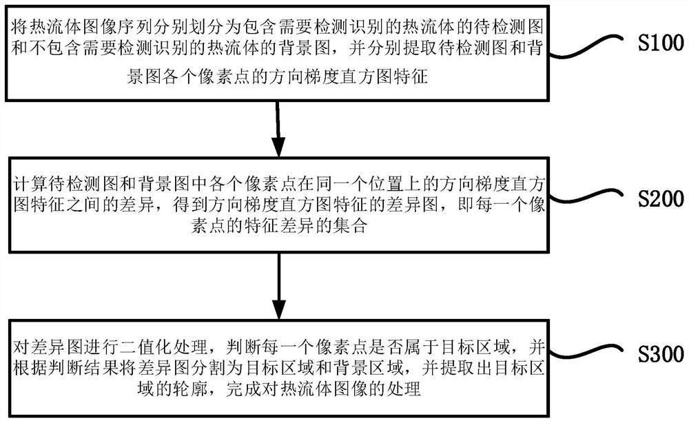
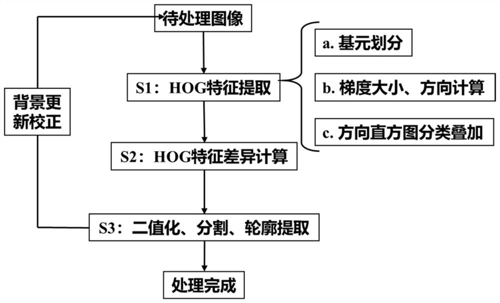
[0053] figure 1 It is a flowchart of a thermal fluid image processing method provided by an embodiment of the present invention.
[0054] Such as figure 1 As shown, the thermal fluid image processing method provided in this embodiment may include the following steps:
[0055] S100, divide the multiple thermal fluid images (image sequences) arranged in time series into the images to be detected containing the thermal fluids to be detected and identified and the background images not to ...
PUM
 Abstract
Description
Claims
Application Information