
Tube threading device for heat exchange tube bundle

A technology of pipe threading device and heat exchange tube bundle, which is used in metal processing, metal processing equipment, manufacturing tools, etc., can solve the problem of difficulty in ensuring stable clamping and conveying effect of pipe fittings, limited clamping and conveying strength of conveying mechanism, and inapplicability to heat exchangers. problems such as intubation operation, to achieve the effect of increasing the number of single intubation, reducing the degree of manual intervention, and optimizing the degree of clamping cooperation

Active Publication Date: 2021-11-30
山东东研智能科技有限公司 +1
View PDF6 Cites 6 Cited by
  • Summary
  • Abstract
  • Description
  • Claims
  • Application Information

AI Technical Summary

Problems solved by technology

Among them, the rubber-hanging transmission wheel group is fixedly installed on the upper cover and the lower cover respectively, and the straight pipe positioning pulley frame only has a supporting effect on the straight pipe, and does not have an auxiliary clamping effect; the pipe threading machine disclosed in this patent has the following disadvantages: The clamping end of the straight pipe is only the part of the rubber-coated transmission wheel, and the action area is small, so it is difficult to ensure the stable clamping and conveying effect of the pipe fittings. It is not suitable for large-weight heat exchange tubes. In addition, the rubber-coated transmission wheel is fixed up and down. The installation structure cannot adjust the clamping degree; based on the above reasons, it cannot be used to wear pipes with heat exchangers
The technical content disclosed in this patent is not applicable to the intubation of heat exchange tubes. The reason is that: because the transport is a soft tube (the tube itself has a deformation amount), and it is not necessary to ensure the accuracy of the transport direction, there is no need for the upper and lower clamping structures to have High clamping fit, and no special design is required for the shape of the notch on the conveyor belt
[0010] In addition, the heat exchange tube threading machine inserts multiple heat exchange tubes at the same time. Due to the limited clamping and conveying strength of the conveying mechanism itself, it is difficult to ensure uniform clamping force on each heat exchange tube.
This is easy to cause, the heat exchange tubes with high clamping degree will have stable delivery, and the heat exchange tubes with low clamping degree will lag in delivery, resulting in asynchronous delivery of multiple tubes
[0011] When the conveying mechanism is used to pass through the heat exchange tubes, if the synchronization problem cannot be solved, the heat exchange tubes will not be able to penetrate the baffles synchronously, and the heat exchange tubes that are transported behind need to be manually operated to pass into the baffles, or , the delivery direction of the lagging heat exchange tube is shifted, resulting in the inability to insert the heat exchange hole of the baffle plate
[0012] Based on the above, the applicant believes that none of the pipe delivery structures in the prior art is suitable for the pipe-through operation of the heat exchanger

Method used


Image

  • Tube threading device for heat exchange tube bundle
  • Tube threading device for heat exchange tube bundle
  • Tube threading device for heat exchange tube bundle

Examples


Embodiment Construction

[0138] The technical solutions in specific embodiments of the present invention will be described in detail and completely below in conjunction with the accompanying drawings. Apparently, the described embodiments are only some specific implementations of the general technical solution of the present invention, but not all implementations. All other embodiments obtained by those skilled in the art based on the general concept of the present invention fall within the protection scope of the present invention.

[0139] In describing the present invention, it is to be understood that the terms "center", "upper", "lower", "front", "rear", "left", "right", "vertical", "horizontal", The orientations or positional relationships indicated by "top", "bottom", "inner", "outer", etc. are based on the orientations or positional relationships shown in the drawings, and are only for the convenience of describing the present invention and simplifying the description, rather than indicating o...


PUM


Abstract

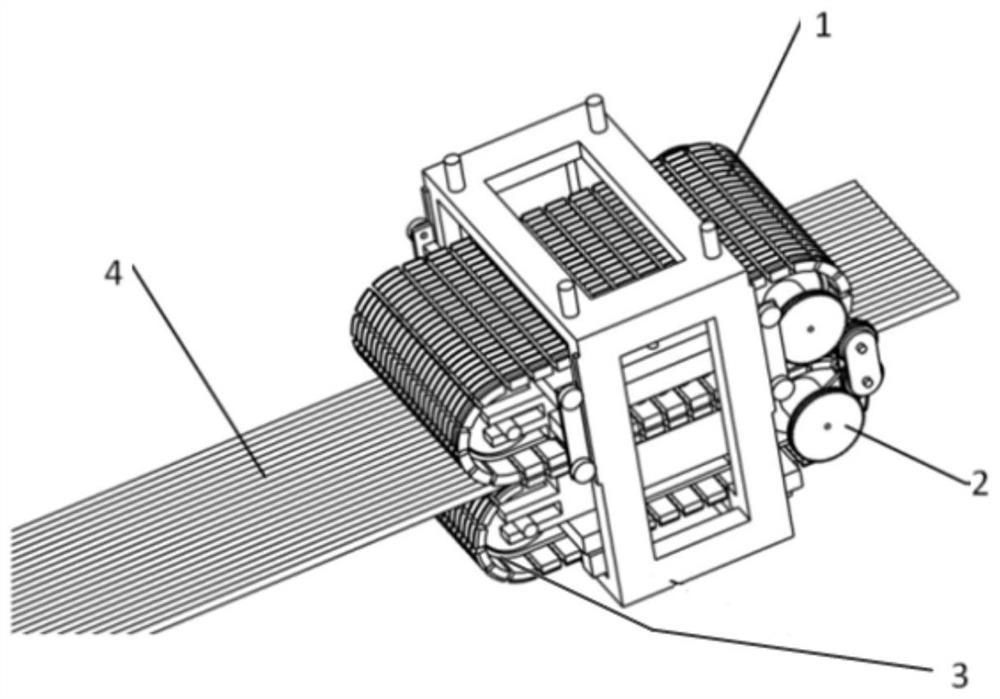
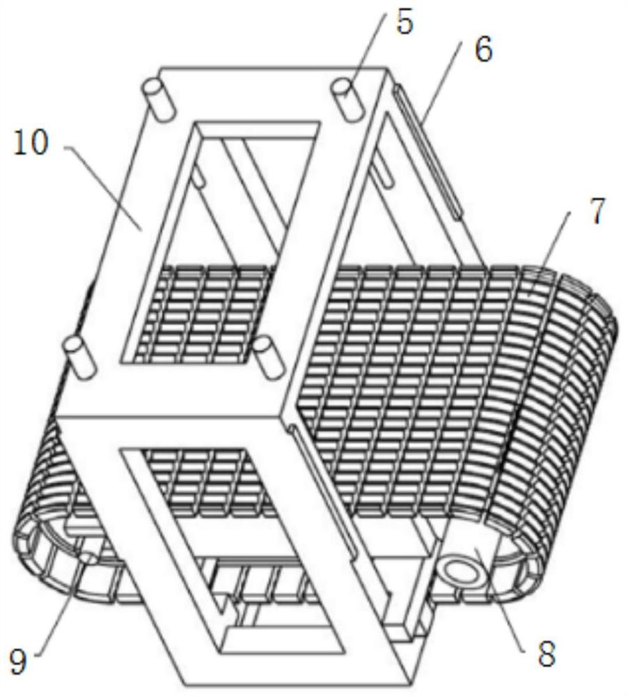
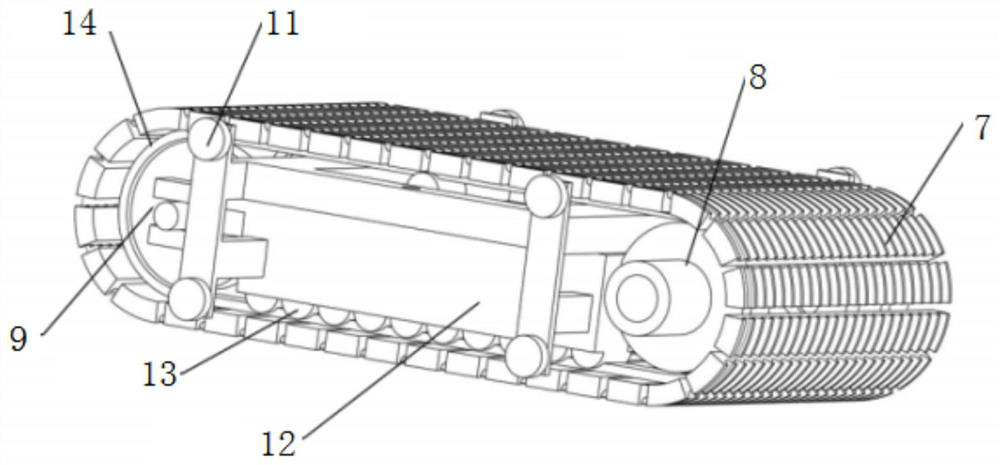
The invention belongs to the field of heat exchanger machining, and particularly relates to a tube threading device for a heat exchange tube bundle. The tube threading device comprises a frame, a fixing and conveying unit, a pressing and conveying unit, and a driving unit, wherein the frame is provided with an open accommodating space, the fixing and conveying unit is positioned in the open accommodating space, the pressing and conveying unit is located in the open accommodating space and located above the fixing and conveying unit, an adjustable space for containing heat exchange tubes is formed between the pressing and conveying unit and the fixing and conveying unit, and the driving unit is used for driving the fixing and conveying unit and the pressing and conveying unit to move. The tube threading device for the heat exchange tube bundle has the beneficial effects that continuous threading of the heat exchange tubes is achieved, the labor intensity of workers is reduced, the number of operators is reduced, cost is saved, the tube threading efficiency is improved, and the heat exchanger production speed is increased.

Description

technical field [0001] The invention belongs to the field of heat exchanger processing, in particular to a heat exchange tube bundle pipe threading device for a heat exchanger. Background technique [0002] A heat exchanger is a device that transfers part of the heat of a hot fluid to a cold fluid, also known as a heat exchanger. Heat exchangers play an important role in chemical, petroleum, power, food and many other industrial productions. In chemical production, heat exchangers can be used as heaters, coolers, condensers, evaporators and reboilers, etc., and are widely used . [0003] Heat exchangers include many categories, among which, common types of tube heat exchangers include fixed tube-sheet heat exchangers, floating head heat exchangers, U-shaped tube heat exchangers, and tube heat exchangers include square or round Different types of baffles according to actual requirements. Baffles are plates used to change the flow direction of fluids. They are often used in ...

Claims


Application Information

Patent Timeline
Patent Type & Authority Applications(China)
IPC IPC(8): B23P19/00
CPCB23P19/001B23P19/00B23P19/006
Inventor 张林于双胡庚乐张新宇韩明顺孟云龙周红兰石岩雷健刘光胜张松汪梦张亚新
Owner 山东东研智能科技有限公司
Learn More