Electro-hydrostatic brake control device for unmanned aerial vehicle and dynamic pressure maintaining method
A technology of brake control and electromechanical hydrostatic, which is applied in the field of aircraft brake control system, can solve the problems of poor reliability, complex structure and high cost of UAV electrostatic hydraulic actuator, and achieve short pressure building time, low power consumption and high response The effect of shortening the time
- Summary
- Abstract
- Description
- Claims
- Application Information
AI Technical Summary
Problems solved by technology
Method used
Image
Examples
Embodiment 1
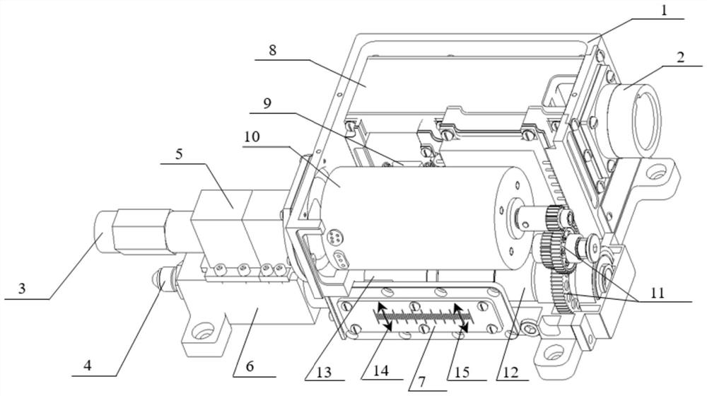
[0038] An unmanned aerial vehicle electrostatic hydraulic brake control device, such as figure 2 As shown, it includes a chassis 1, a controller 8, a motor 10, a gear assembly and a hydraulic assembly;
[0039] The controller 8 is installed inside the chassis 1, and a motor 10 is installed on the side of the controller 8, and the motor 10 is electrically connected to the controller 8; the hydraulic assembly includes a hydraulic cylinder 6 and a test chamber 5, and the hydraulic cylinder 6 is installed through the chassis 1. The cylinder 6 is provided with a piston 13, and the test cavity 5 is installed on the upper part of the hydraulic cylinder 6 and connected with the hydraulic cylinder 6; the motor 10 is connected with the piston 13 through a gear assembly.
Embodiment 2
[0041] Except for the following content, all the other contents are the same as in Example 1.
[0042] A connector 9 is left on the outside of the controller 8, and the leads of the motor 10, temperature sensor 16 and pressure sensor 17 of the electro-hydraulic actuator are connected to the connector 9. The controller 8 and the electro-hydraulic actuator are installed in the same case 1, and the electrical connection and separation can be conveniently performed by plugging in the connector 9. There is a circular connector 2 outside the brake control device for power supply and communication; the connector 2 is electrically connected to the controller 8 and the motor 10 respectively.
[0043] The test chamber 5 is provided with an oil outlet port 4 and an oil replenishment port 3. The oil outlet port 4 is used to connect a hose to send out hydraulic oil; the oil replenishment port 4 is used to connect an oil injection pipe to replenish hydraulic oil; the ball screw pair 12 The...
Embodiment 3
[0045] Except for the following content, all the other contents are the same as in Example 1.
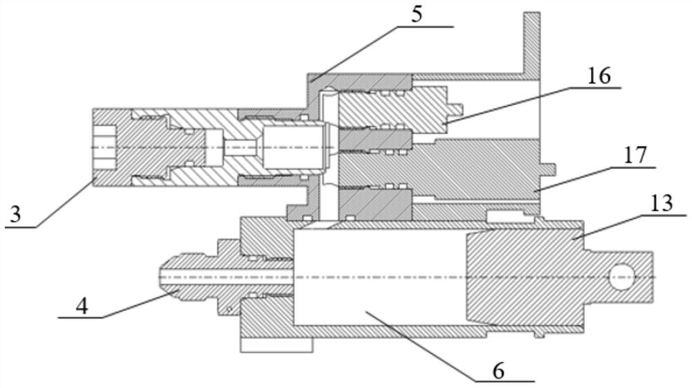
[0046] like image 3 As shown, the test cavity 5 and the hydraulic cylinder 6 are sealed by an O-shaped rubber ring to form a connector, and at the same time provide a channel for the oil supply interface 3 . The hydraulic assembly also includes a temperature sensor 16 and a pressure sensor 17; both the temperature sensor 16 and the pressure sensor 17 are installed in the test chamber 5 for detecting oil pressure and oil temperature. The test chamber 5 is provided with an oil outlet interface 4 and an oil supply interface 3. In order to ensure the oil pressure dynamic seal between the outer circle of the piston and the inner wall of the hydraulic cylinder, 4 O-rings are designed on the piston 13; The oil and oil supply port 3 adopts a check valve and sealing design; the oil outlet port 4 adopts a standard 74° conical sealing design, which is convenient for connecting hoses. An oil...
PUM
 Abstract
Description
Claims
Application Information
 - R&D
- Intellectual Property
- Life Sciences
- Materials
- Tech Scout
- Unparalleled Data Quality
- Higher Quality Content
- 60% Fewer Hallucinations
Browse by: Latest US Patents, China's latest patents, Technical Efficacy Thesaurus, Application Domain, Technology Topic, Popular Technical Reports.
© 2025 PatSnap. All rights reserved.Legal|Privacy policy|Modern Slavery Act Transparency Statement|Sitemap|About US| Contact US: help@patsnap.com


