
Electric welding forming method for large-size amorphous alloys and bulk amorphous alloys

An amorphous alloy, welding forming technology, applied in non-electric welding equipment, welding equipment, laser welding equipment, etc., can solve problems affecting welding quality, uneven heat, slow welding speed, etc., to improve welding quality and welding efficiency, Guaranteed heating temperature and uniform heat production effect

Pending Publication Date: 2021-12-03
GUANGDONG UNIV OF TECH
View PDF12 Cites 0 Cited by
  • Summary
  • Abstract
  • Description
  • Claims
  • Application Information

AI Technical Summary

Problems solved by technology

At present, using the superplasticity of amorphous alloys, a series of processing methods for forming large-scale amorphous alloys have been produced, such as using laser welding technology, friction welding technology, resistance welding technology and other methods to process amorphous alloys to obtain larger However, the amorphous alloys obtained by these processing methods still have some problems, such as the occurrence of crystallization, unstable welding quality, slow welding speed and poor welding strength.
[0004] For example, the patent CN201410133025.9 discloses a laser welding method for copper-based amorphous alloys: under the protection of an inert atmosphere, pulse laser or continuous wave laser is used to make the welding parts of the substrate to be welded and the welded part reach above their respective melting points Joining is carried out in a molten state, and based on the TTT diagram, the base material to be welded and the weldment are welded without crystallization reaction, although this method solves the welding problem of copper-based amorphous alloys with a certain structure , but due to the limitations of laser processing itself, it is difficult to apply to the welding of amorphous alloys with large thickness
Patent CN202010469406.X discloses an ultrasonic friction welding forming method for large-sized amorphous alloys: clamping the microstructured amorphous alloy on an ultrasonic welding system for rotational friction welding, although this method solves the problem of rotational friction Inhomogeneity of welding heat, but there are still deficiencies in weld quality and welding efficiency
Patent CN201410379335.9 discloses a resistance welding method for amorphous alloys: contact the amorphous alloy with the welding workpiece, apply pressure to the electrodes and use the resistance heat generated by the current to heat the amorphous alloy and the welding workpiece to above their respective melting points or Reach their respective supercooled liquid phase regions, and use the TTT diagram as a benchmark to complete the welding of the welding workpiece and the amorphous alloy without crystallization reaction. Although this method solves the welding problem between the amorphous alloy and the welding workpiece, However, it takes a long time to heat the amorphous alloy and the welded workpiece with resistance heat, and heating the entire welded workpiece will easily cause uneven heat, which will affect the welding quality.

Method used


Image

  • Electric welding forming method for large-size amorphous alloys and bulk amorphous alloys
  • Electric welding forming method for large-size amorphous alloys and bulk amorphous alloys
  • Electric welding forming method for large-size amorphous alloys and bulk amorphous alloys

Examples


Embodiment 1

[0042] A discharge welding forming method for large-size amorphous alloys disclosed in this embodiment includes the following steps:

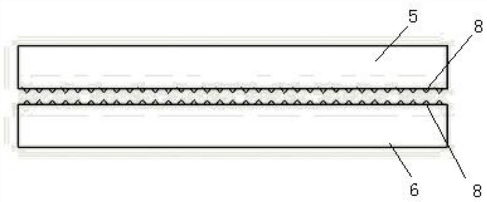
[0043] S1: Laser processing the surfaces of the first amorphous alloy 5 and the second amorphous alloy 6 to be welded as follows figure 2 The tapered microstructure 8 is shown. Wherein the composition of the first amorphous alloy 5 and the second amorphous alloy 6 is Zr 66 Al 18 Ni 26 , Tg is 398.85°C, Tx is 434.45°C, the processed amorphous alloy is placed in ethanol for ultrasonic cleaning for 5 minutes, and then dried in a drying oven for 15 minutes to ensure that the surface is free of pollutants.

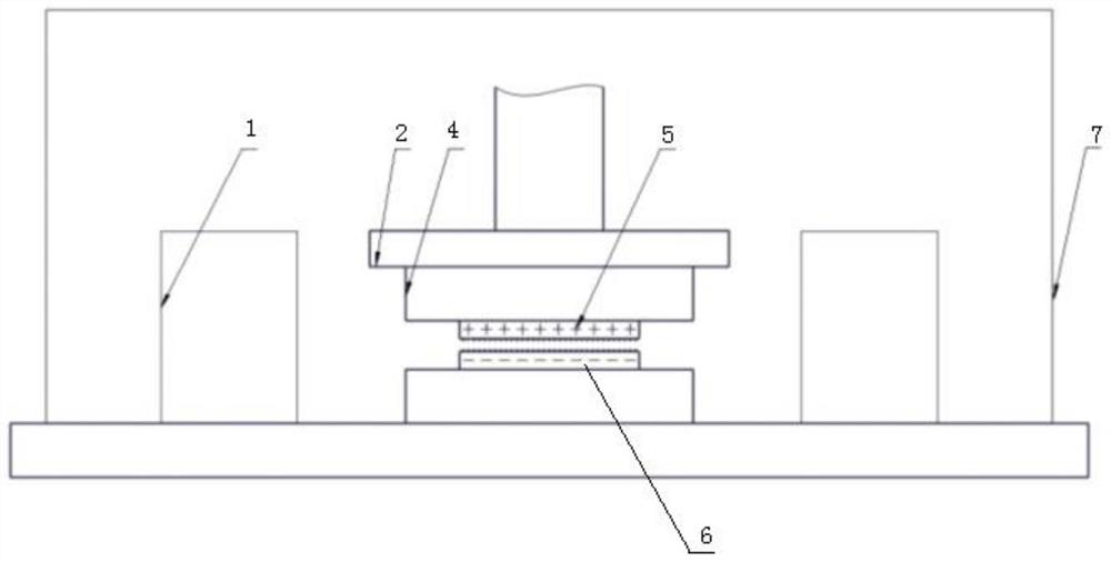
[0044] S2: install the processed first amorphous alloy 5 and the second amorphous alloy 6 on the figure 1 On the upper and lower clamps 4 of the shown precision mobile platform, then adjust the precision mobile platform so that the microstructure surfaces of the first amorphous alloy 5 and the second amorphous alloy 6 are opposite, and the ...

Embodiment 2

[0049] A discharge welding forming method for large-size amorphous alloys disclosed in this embodiment includes the following steps:

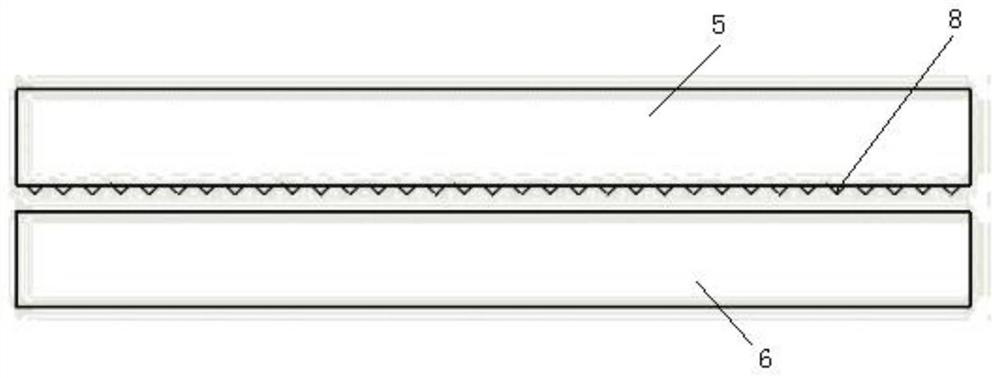
[0050] S1: the surface of the first amorphous alloy 5 to be welded and the surface of the second amorphous alloy 6 are processed by laser such as image 3 The shown tapered microstructures 8 and tapered hole microstructures 8 (not shown in the figure). Wherein the composition of the first amorphous alloy 5 is Cu 54 Zr 42.5 Al 3.5 , Tg is 443.85°C, and Tx is 491.85°C. The composition of the second amorphous alloy 6 is Zr 60 Al 13.3 co 26.7 , Tg is 444.85 ° C, Tx is 483.85 ° C, the processed amorphous alloy is placed in ethanol for ultrasonic cleaning for 5 minutes, and then dried in a drying oven for 15 minutes to ensure that the surface is free of pollutants.

[0051] S2: install the processed first amorphous alloy 5 and the second amorphous alloy 6 on the figure 1 On the upper and lower clamps 4 of the shown precision mobile platform, ...

Embodiment 3

[0056] A discharge welding forming method for large-size amorphous alloys disclosed in this embodiment includes the following steps:

[0057] S1: the surface of the first amorphous alloy 5 to be welded and the surface of the second amorphous alloy 6 are processed by laser such as Figure 4 As shown in the millimeter-scale microstructure 8, a nano-scale conical microstructure is further processed on the millimeter-scale microstructure 8, so that more discharge tips can be added. Wherein the composition of the first amorphous alloy 5 is Fe 67 co 10 Tb 3 B 20 , Tg is 521.85°C, and Tx is 557.85°C. The composition of the second amorphous alloy 6 is Zr 55 Al 20 co 25 , Tg is 490.85 ° C, Tx is 565.85 ° C, the processed amorphous alloy is placed in ethanol for ultrasonic cleaning for 5 minutes, and then dried in a drying oven for 15 minutes to ensure that the surface is free of pollutants.

[0058] S2: install the processed first amorphous alloy 5 and the second amorphous allo...


PUM

PropertyMeasurementUnit
Magnetic inductionaaaaaaaaaa

Abstract

The invention relates to the technical field of amorphous alloy connection, in particular to an electric discharge welding forming method and an electric heating welding forming method for large-size amorphous alloys. The electric discharge welding forming method comprises the following steps that S1, the first amorphous alloy and the second amorphous alloy are adopted, and tip microstructures are machined on to-be-welded interfaces; S2, the to-be-welded interface of the first amorphous alloy and the to-be-welded interface of the second amorphous alloy are made to be opposite, and a certain distance is reserved between the to-be-welded interface of the first amorphous alloy and the to-be-welded interface of the second amorphous alloy; S3, magnetic fields are applied to both the first amorphous alloy and the second amorphous alloy, and the first amorphous alloy and the second amorphous alloy are both connected to an electric discharge system; and S4, the electric discharge system is started, then the first amorphous alloy and the second amorphous alloy are driven to be pressed, and pressing pressure is applied till the first amorphous alloy and the second amorphous alloy are welded and formed. The electric discharge welding method has the advantages of being high in welding speed and high in welding quality, and the electric heating welding forming method improves the heating uniformity by increasing the magnetic field control and an auxiliary heating device.

Description

technical field [0001] The invention relates to the technical field of amorphous alloy connection, in particular to an electric welding forming method for large-size amorphous alloys and bulk amorphous alloys, and in particular to a discharge welding forming method for large-size amorphous alloys And electric heating welding forming method. Background technique [0002] Amorphous alloy (also known as metallic glass) is a metal whose internal atomic arrangement is long-range disordered like glass. It has excellent mechanical, physical and chemical properties of general metals and glasses. It has broad applications in aviation, automobile, medical and other fields. Application prospect. However, the size of the original amorphous alloys is mostly limited to centimeters, which greatly limits the application of amorphous alloys in the industrial field. Therefore, how to prepare large-sized amorphous alloys is a technical difficulty in expanding the application of amorphous allo...

Claims


Application Information

Patent Timeline
IPC IPC(8): B23K20/00B23K20/24B23K20/26B23K26/346
CPCB23K20/00B23K20/24B23K20/26B23K26/346C22C45/10C22C45/001C22C45/02
Inventor 王成勇王相煜唐梓敏甄铁城陈伟专
Owner GUANGDONG UNIV OF TECH
Learn More