
Urea catalytic hydrolysis reactor for flue gas denitrification and method

A urea catalytic hydrolysis and reactor technology, which is applied in the field of urea catalytic hydrolysis reactors for flue gas denitrification, can solve the problems of wastewater containing phosphorus compounds, difficult replacement of solid catalysts, blockage of hydrolysis intermediate products, etc., so as to improve the hydrolysis reaction rate and shorten the Hydrolysis reaction time, anti-corrosion effect

Pending Publication Date: 2021-12-07
XIAN THERMAL POWER RES INST CO LTD +1
View PDF16 Cites 0 Cited by
  • Summary
  • Abstract
  • Description
  • Claims
  • Application Information

AI Technical Summary

Problems solved by technology

[0010] During the use of existing hydrolysis devices, the common problems are large reactor volume, slow load response rate, and blockage of sewage pipes by hydrolysis intermediate products. At the same time, existing hydrolysis devices generally use hydrogen phosphate or dihydrogen phosphate, etc. The liquid hydrolysis catalyst has a large loss and needs to be replenished at any time, and will cause phosphorus compounds in the wastewater, and direct discharge will cause eutrophication of the water body; in addition, the solid catalyst proposed in the relevant patent is difficult to arrange and replace in the narrow reactor space

Method used


Image

  • Urea catalytic hydrolysis reactor for flue gas denitrification and method
  • Urea catalytic hydrolysis reactor for flue gas denitrification and method
  • Urea catalytic hydrolysis reactor for flue gas denitrification and method

Examples


Embodiment Construction

[0037] The present invention will be further described in detail below in conjunction with specific embodiments, which are explanations of the present invention rather than limitations.

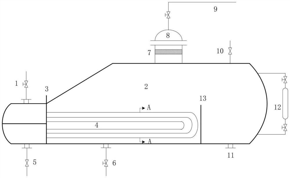
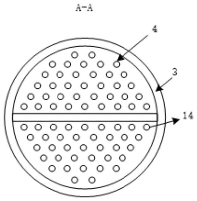
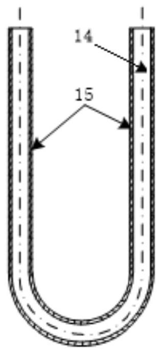
[0038] A kind of flue gas denitrification urea catalytic hydrolysis reactor of the present invention, such as figure 1 As shown, it includes kettle body 2, saturated steam inlet 1, plug 3, coil cluster 4, drain outlet 5, urea solution inlet 6, demister 7, ammonia outlet 8, delivery pipeline 9, safety valve 10, isolation Plate 13, sewage outlet 11, liquid level gauge 12, coil pipe 14 and catalyst coating 15;

[0039] Such as figure 1 As shown, the urea solution inlet 6 and the sewage outlet 11 are located at the bottom of the kettle body 2; the ammonia gas outlet 8 and the safety valve 10 are arranged on the top of the kettle body 2; the partition plate 13 is arranged on the inner bottom surface of the kettle body 2 The liquid level gauge 12 is connected to the kettle body 2; the delivery pi...


PUM


Abstract

The invention relates to a thermal power plant flue gas denitration technology, in particular to a urea catalytic hydrolysis reactor for flue gas denitration and a method. The system comprises a kettle body and a coil pipe cluster fixedly arranged in the kettle body through a plug; a urea solution inlet is formed in the bottom of the kettle body, and an ammonia outlet is formed in the top of the kettle body; a saturated steam inlet and a drain outlet are respectively formed in the outer side of the plug; the coil pipe cluster comprises a plurality of coil pipes inserted into the kettle body; the end part of the coil pipe is fixed with the inner side of the plug, the outer surface of the coil pipe is coated with a catalyst coating, the inlet end of the coil pipe is communicated with the saturated steam inlet, the outlet end of the coil pipe is communicated with the drain outlet, and the coil pipe is a U-shaped pipe made of a 316L stainless steel material; a partition plate is arranged on the bottom surface in the kettle body; the coil pipe cluster is arranged at one side of the partition plate, and the bottom surface of the kettle body on the other side is provided with a drain outlet. The reactor has the advantages of economy, feasibility, simple structure, convenience in catalyst supplement and long service life.

Description

technical field [0001] The invention relates to flue gas denitrification technology in thermal power plants, in particular to a urea catalytic hydrolysis reactor and method for flue gas denitrification. Background technique [0002] Selective catalytic reduction (SCR) is currently the most widely used flue gas denitrification technology in my country, and ammonia is mainly used as the reducing agent in the process. There are three sources of ammonia: liquid ammonia, urea and ammonia water. In recent years, domestic and foreign power generation companies have paid more and more attention to the potential dangers in the use of liquid ammonia. In the next few years, the market demand for urea ammonia production technology will be huge. Urea ammonia production includes two methods: pyrolysis and hydrolysis. The hydrolysis technology has the characteristics of high urea conversion rate, few by-products, and only low-grade steam can meet the heat demand of hydrolysis reaction. It...

Claims


Application Information

Patent Timeline
IPC IPC(8): B01J19/24C01C1/08
CPCB01J19/24B01J19/0053B01J19/0013C01C1/086
Inventor 张向宇向小凤陆续张波徐宏杰姚伟
Owner XIAN THERMAL POWER RES INST CO LTD
Learn More