Bit synchronization method of digital communication data transmission system

A bit synchronization and data information technology, applied in the field of signal processing, can solve the problems of inability to extract bit synchronization signal data symbols, prolonged processing, long time consumption, etc., to avoid multi-sampling or missing sampling, improve real-time processing, reduce The effect of processing time

Pending Publication Date: 2021-12-07
SHAANXI CHANGLING ELECTRONICS TECH
View PDF0 Cites 0 Cited by
  • Summary
  • Abstract
  • Description
  • Claims
  • Application Information

AI Technical Summary

Problems solved by technology

If the number of consecutive symbols is large, this phase error will easily cause the phase-locked loop to lose lock and lose synchronization after continuous accumulation. time consuming
[0009] 2. Large amount of calculation, many hardware resources and easy bit errors
[0010] A digital phase-locked loop is a feedback loop, mainly including a filter, a timing error detector, and a numerically controlled oscillator NCO module. It will inevitably use mathematical operations of multiplication and addition and multi-level registers, with a large amount of calculation and a long processing delay. , consume more hardware resources
Moreover, when the phase error between the synchronous clock signal at the receiving end and the optimal sampling time continuously accumulates to exceed half a symbol bit width, the problem of multi-sampling or missing sampling will occur when the baseband signal is sampled and judged, resulting in demodulation data error
[0011] The deficiencies in the above two aspects will lead to the inability to quickly and effectively extract the bit synchronization signal to demodulate the data symbols when the data transmission rate is high and the bandwidth is large.

Method used


Image

  • Bit synchronization method of digital communication data transmission system
  • Bit synchronization method of digital communication data transmission system

Examples


Embodiment Construction

[0033] Embodiments of the present invention will be described in detail below in conjunction with the accompanying drawings.

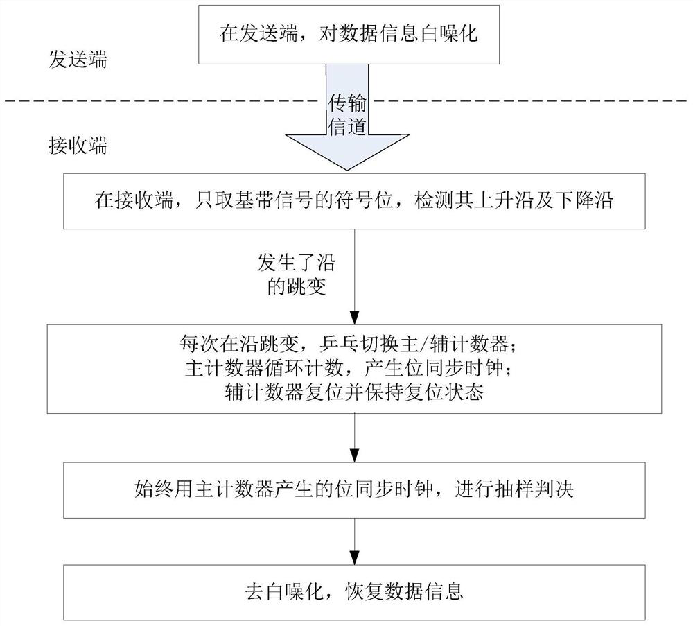
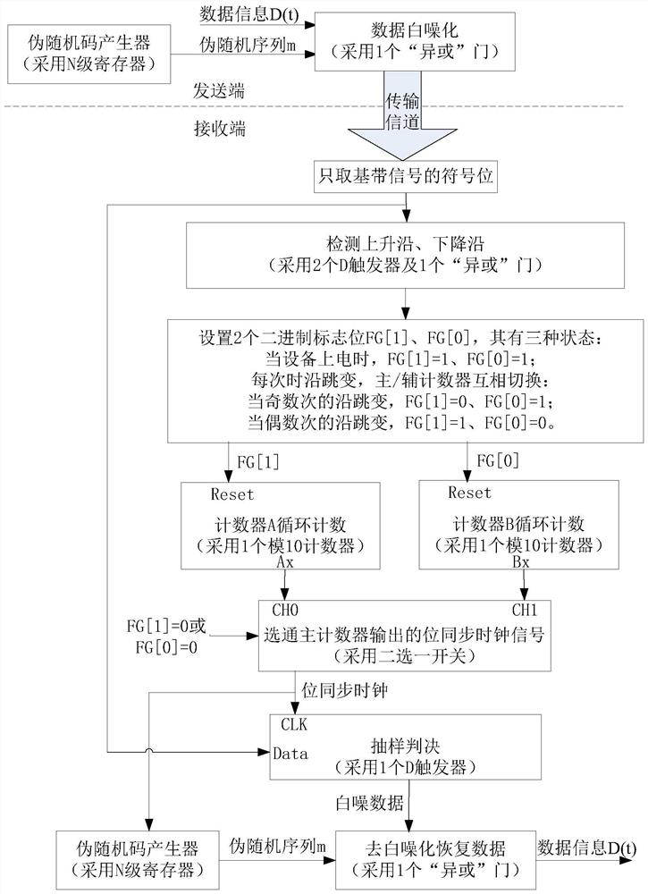
[0034] The present invention is a bit synchronization method of a digital communication data transmission system, which is suitable for a frequency band transmission system of digital communication, and the bit synchronization of the present invention does not take carrier synchronization of a frequency band signal as a precondition.

[0035] refer to figure 1 , the realization process of the present invention is: choose a symbol length to be 2 N The pseudo-random sequence m of -1 uses the pseudo-random sequence m to whiten the data information at the sending end, so that the data has pseudo-randomness; at the receiving end, only the sign bit of the baseband signal is taken, and the signal waveform is changed into a rectangular pulse signal. And change the bipolar signal into a unipolar signal, get the baseband signal waveform of the receiving end aft...


PUM


Abstract

The invention discloses a bit synchronization method of a digital communication data transmission system, which mainly solves the problems of long synchronization establishment time and more occupied resources in the existing method. According to the scheme, a pseudo-random sequence is selected to carry out white noise processing on data information sent to a sending end; taking the sign bit of the baseband signal of the receiving end, and detecting the edge jump of the sign bit; two modulo 10 counters are designed as a main counter and an auxiliary counter; in an initial state, the two counters are both kept in a reset state; during edge hopping, the main / auxiliary counter performs ping-pong identity switching work, the main counter circularly counts to generate a bit synchronization clock signal, and the auxiliary counter is reset and kept in a reset state; and the sampling decision device always carries out sampling decision on the baseband signal sign bit of the receiving end by using the bit synchronization clock signal generated by the main counter, and recovers data information. Bit synchronization can be achieved within one code element time, the real-time performance of obtaining the bit synchronization clock signal is high, occupation of hardware resources is reduced, and the method can be used for communication data transmission and electronic navigation.

Description

technical field [0001] The invention belongs to the technical field of signal processing, in particular to a bit synchronization method, which can be used for digital communication data transmission and electronic navigation. Background technique [0002] In the digital communication data transmission system, the sending end sends data sequentially according to the symbol rate, and the bit synchronization function module of the receiving end generates a bit synchronization clock signal whose repetition frequency is the same as the symbol rate and whose phase is consistent with the best sampling time. It is at the center of each symbol at all times, which is the maximum value of the eye diagram. Sampling judgment at this moment can avoid data errors and realize correct sampling and recovery of data. Bit synchronization is the best sampling time to capture and track symbols . [0003] The data symbol sequence is a non-return-to-zero random binary signal, which itself does not...

Claims


Application Information

Patent Timeline
Patent Type & Authority Applications(China)
IPC IPC(8): H04L7/00H04L7/04
CPCH04L7/0008H04L7/0054H04L7/043
Inventor 陈华
Owner SHAANXI CHANGLING ELECTRONICS TECH
Why Eureka
Try Eureka