Photovoltaic inverter capable of suppressing leakage current and control method of inverter

A photovoltaic inverter, leakage current technology, applied in photovoltaic power generation, AC power input conversion to DC power output, electrical components and other directions, can solve the complex topology of the inverter, high performance requirements of switching devices, and low DC bus voltage. and other problems, to achieve the effect of simple control scheme, less power devices, and realization of common mode voltage

Active Publication Date: 2021-12-10
ANHUI UNIVERSITY OF TECHNOLOGY
View PDF6 Cites 0 Cited by
  • Summary
  • Abstract
  • Description
  • Claims
  • Application Information

AI Technical Summary

Problems solved by technology

In 2002, Peng Fangzheng proposed the Z-source inverter, which solved some shortcomings of the traditional voltage source inverter. The Z-source inverter uses the controllable direct connection of the upper and lower bridge arm power switch tubes to increase the DC bus voltage on the input side of the inverter. , so as to increase the output AC voltage, but this inverter topology is more complex, there is a start-up shock oscillation, the DC bus voltage is lower than the capacitor voltage, and the voltage gain is limited by the direct duty cycle and modulation ratio, etc., which is far from practical application. for further study
Its disadvantage is that the starting point of the inverter is to reduce the leakage current in the voltage conversion of the photovoltaic array. There are many switching devices, which increases the volume of the circuit, and 2 / 3 of the switching devices work at high frequency. The performance requirements of switching devices are high, and the loss is large, which reduces the efficiency of the inverter

Method used


Image

  • Photovoltaic inverter capable of suppressing leakage current and control method of inverter
  • Photovoltaic inverter capable of suppressing leakage current and control method of inverter
  • Photovoltaic inverter capable of suppressing leakage current and control method of inverter

Examples


Embodiment 1

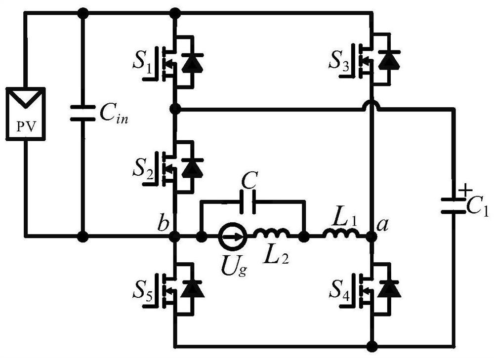
[0045] like figure 1 , a photovoltaic inverter that can suppress leakage current, including a power switch tube S 1 , S 2 , S 3 , S 4 and S 5 , switched capacitor C 1 ; Power switch tube S 1 , S 3 The A terminal of the terminal is connected to the DC input side (that is, by the photovoltaic power board PV and the capacitor C in Composed of parallel circuit) at one end; power switch tube S 1 The C terminal and the switched capacitor C 1 Connected at one end, and at the same time connected to the power switch tube S 2 The A terminal is connected; the switching capacitor C 1 The other end of the power switch tube S 4 , S 5 The C terminal is connected; the power switch tube S 3 The C terminal and the power switch tube S 4 Terminal A of A is connected to node a; the power switch tube S 2 The C terminal and the power switch tube S 5 The terminal A of A is connected to node b; nodes a and b form the output terminal, and the load terminal is connected between nodes a a...

Embodiment 2

[0048] like figure 1 , a photovoltaic inverter capable of suppressing leakage current in this embodiment, on the basis of Embodiment 1, further includes a filter, and the filter may be of LC or LCL type. The nodes a and b are connected to the input of the filter, and the output of the filter is connected to the load R 0 or grid connection.

[0049] When the inverter operates independently, the filter is LC type, including filter inductor L 1 and filter capacitor C, filter inductor L 1 One end is connected to node a, and the filter inductor L 1 The other end is connected to the filter capacitor C, and the other end is connected to the load R 0 Connected at one end, the other end of the filter capacitor C and the load R 0 The other end is connected to node b.

[0050] When the inverter is connected to the grid, the filter is LCL type, including the inverter side filter inductor L 1 , filter capacitor C and grid-connected side filter inductor L 2 , Inverter side filter in...

Embodiment 3

[0074] A photovoltaic inverter capable of suppressing leakage current in this embodiment has the same basic structure as that in Embodiment 1 or 2, and further, due to the capacitance C 1 As an energy storage element, it plays the role of energy conversion, and the capacitor C 1 It is a non-polar capacitor, which makes the circuit work reliably and increases the working life of the circuit; its control method is the same as that in Embodiment 2.


PUM


Abstract

The invention discloses a photovoltaic inverter capable of suppressing leakage current and a control method of the inverter, and belongs to the technical field of power electronic converters. The photovoltaic inverter comprsies power switch tubes S1, S2, S3, S4 and S5, diodes D1, D2 and D3 and a switch capacitor C1. The power switch tubes S1, S2 and S5 and the power switch tubes S3 and S4 form two bridge arms of the inverter bridge, one end of the switch capacitor C1 is connected between the power switch tubes S1 and S2, and the other end of the switch capacitor C1 is connected between the power switch tubes S4 and S5. In the positive half cycle of the alternating current output waveform, the direct current input side directly provides energy for the load end; and in the negative half cycle, the switched capacitor C1 provides energy for the load end. The direct current side voltage negative electrode in the circuit is directly connected with the alternating current side ground wire, so that generation of leakage current in the circuit can be inhibited from the structural characteristic. Aiming at the problem of current leakage of the existing grid-connected inverter, the method is high in efficiency and obvious in reliability advantage.

Description

technical field [0001] The invention relates to the technical field of power electronic converters, in particular to a photovoltaic inverter capable of suppressing leakage current and a control method thereof. Background technique [0002] In the current context of increasingly tense global energy supply, technologies such as the control and conversion of renewable energy distributed power generation, AC starter control, electric vehicle drive, and new starter power generation are all inseparable from power electronic inverter technology. Therefore, it is of great practical significance to develop a boost inverter technology with high efficiency, high reliability, high power density and small size. [0003] The traditional low-power inverter system is mainly realized by two stages, the DC boost circuit and the inverter circuit. The inverter circuit generally adopts a full-bridge structure, and there are many switching devices, which increases the cost of the system and the c...

Claims


Application Information

Patent Timeline
Patent Type & Authority Applications(China)
IPC IPC(8): H02M7/5387H02M1/32H02M1/088H02M1/14
CPCH02M7/53871H02M1/32H02M1/088H02M1/14Y02E10/56
Inventor 胡雪峰林鑫程赫费晨进余振海张乔
Owner ANHUI UNIVERSITY OF TECHNOLOGY
Why Eureka
Try Eureka