
Efficient microwave excitation gas discharge equipment

A gas discharge and microwave technology, applied to electrical components, plasma, etc., can solve problems such as difficulty in achieving optimal working conditions, reduced energy efficiency, and reduced energy efficiency

Pending Publication Date: 2021-12-10
成都市吉亨特科技有限公司
View PDF0 Cites 0 Cited by
  • Summary
  • Abstract
  • Description
  • Claims
  • Application Information

AI Technical Summary

Problems solved by technology

However, this method has the following disadvantages: 1) the insertion loss of the matching circuit is relatively large, which seriously reduces the energy efficiency of the scheme
2) In the commonly used microwave frequency band of 2450MHz, the power capacity of the lumped parameter circuit is relatively small
The application of this solution in the industrial and environmental protection fields is limited by the power capacity
3) For processing errors and parameter errors of components, this solution lacks adjustability, and it is difficult to achieve the best working condition
4) This solution requires the frequency switching of the microwave source during ignition and operation, which increases the manufacturing cost of the microwave source
5) For the current high-power magnetron with the lowest unit power price, due to its wide frequency spectrum and unstable operating frequency, the matching circuit further reduces energy efficiency due to insufficient operating bandwidth

Method used


Image

  • Efficient microwave excitation gas discharge equipment
  • Efficient microwave excitation gas discharge equipment
  • Efficient microwave excitation gas discharge equipment

Examples


Embodiment 1

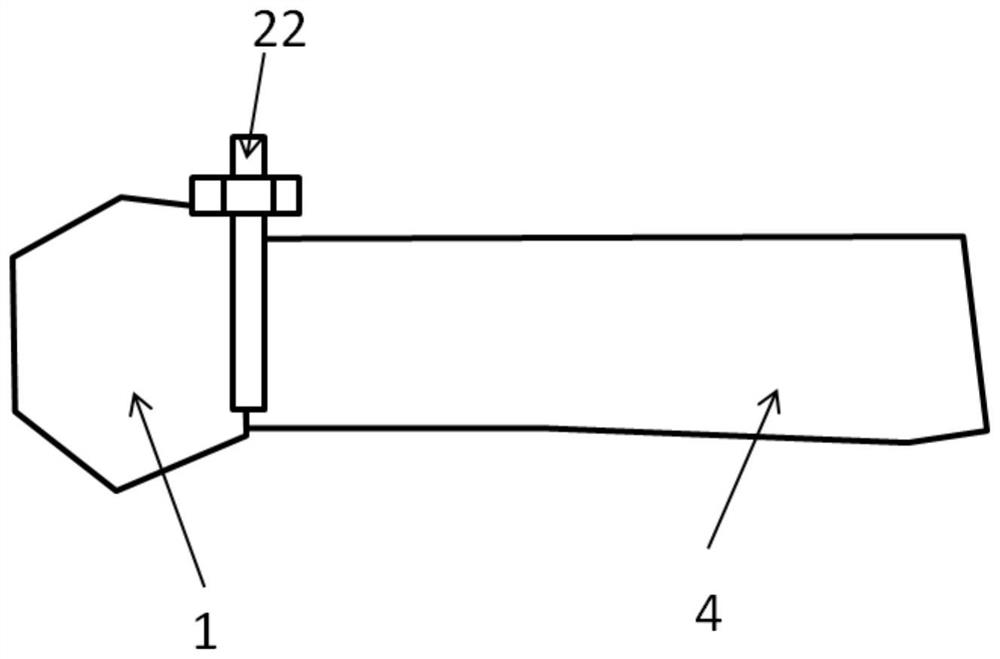
[0034] Such as figure 1 shown.

[0035] A high-efficiency microwave-excited gas discharge device, including a microwave source 1 with an operating frequency of f0 and a micro-nonlinear device 4 connected in sequence; the micro-non-linear device 4 has two state, a small signal state and a large signal state; a coupling structure 22 is arranged between the microwave source 1 and the micro nonlinear device 4; the coupling structure 22 has two states, and the coupling structure 22 The first state corresponds to a weak coupling state, and the second state of the coupling structure 22 corresponds to a strong coupling state; after the micro nonlinear device 4 changes from a small signal state to a large signal state, the coupling structure 22 switch between the first state and the second state.

[0036] There is gas inside the micro-nonlinear device 4, which can break down and generate plasma under the action of sufficiently high-power microwaves.

[0037] The coupling structure 2...

Embodiment 2

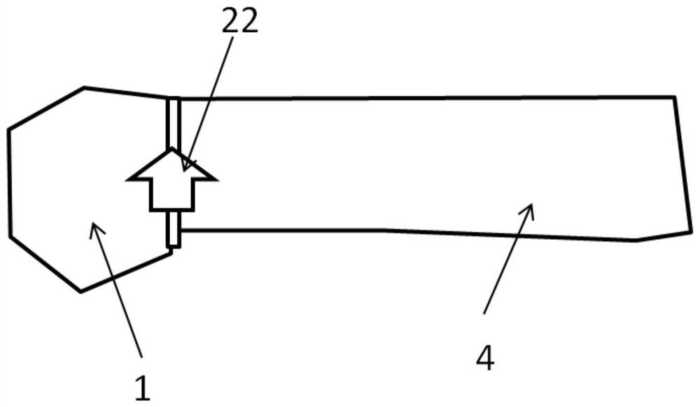
[0040] Such as figure 2 shown.

[0041] Compared with implementation example 1, the only difference is:

[0042] The coupling structure 22 is a diode.

Embodiment 3

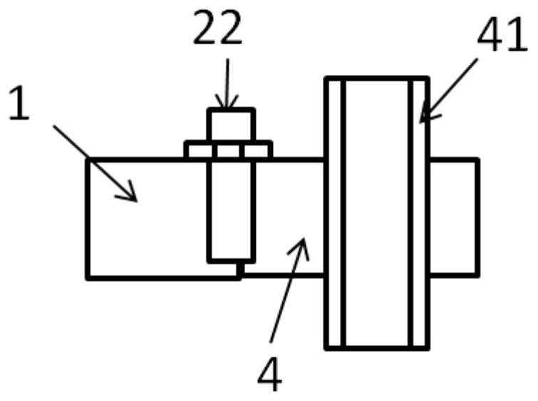
[0044] Such as image 3 shown.

[0045] Compared with implementation example 1, the only difference is:

[0046] The high-efficiency microwave excited gas discharge device is a plasma torch. Both the output end of the microwave source and the nonlinear device 4 are rectangular waveguides. A dielectric tube 41 is arranged in the rectangular waveguide, and the dielectric tube 41 passes through the waveguide. In the waveguide, gas is input from one end of the dielectric tube 41 , is ionized through the dielectric tube 41 , forms high-temperature plasma, and is ejected from the other end of the dielectric tube 41 .


PUM


Abstract

The invention discloses a design scheme of efficient microwave excitation gas discharge equipment. The design scheme is characterized in that a coupling structure capable of switching states is arranged in the equipment; and during ignition, the coupling structure works in a weakly-coupled first state, strong resonance with the resonant frequency the same as the working frequency of a microwave source is formed in a nonlinear device, ignition is smooth, then the coupling structure works in an almost straight-through second state, almost all microwaves generated by the microwave source are absorbed by the nonlinear device, and the equipment can work efficiently. According to the invention, the equipment can be applied to disinfection and sterilization treatment of various gases and liquids, high-brightness and long-service-life illuminating lamps and microwave plasma torches.

Description

technical field [0001] The invention relates to a high-efficiency microwave excitation gas discharge device. Specifically, it relates to a high-efficiency gas discharge device that uses a two-state working coupling structure to realize low-power automatic ignition and work of the gas plasma discharge device. Background technique [0002] Under the action of high-power microwaves, the gas will be ionized, generate plasma and emit light. Electrodeless ultraviolet lamps lit by microwaves have the advantages of high brightness, long life and high luminous efficiency. They can be widely used in air and drinking water sterilization, and can also be used in industrial waste gas and industrial wastewater treatment and other fields. The plasma torch generated by using microwave ionized gas The microwave plasma torch realized by using microwave ionized gas has the characteristics of high temperature, no pollution, and can be quickly started and stopped. It is used in motor vehicle en...

Claims


Application Information

Patent Timeline
Patent Type & Authority Applications(China)
IPC IPC(8): H05H1/46
CPCH05H1/46
Inventor 王清源
Owner 成都市吉亨特科技有限公司
Learn More