Photovoltaic and photo-thermal integrated building material photovoltaic module

A photovoltaic module and photothermal technology, applied in the field of solar cells, can solve problems such as the decline of photoelectric conversion efficiency, and achieve the effects of easy promotion, no risk of explosion, and low metal consumption

Pending Publication Date: 2021-12-14
浙大宁波理工学院
View PDF15 Cites 0 Cited by
  • Summary
  • Abstract
  • Description
  • Claims
  • Application Information

AI Technical Summary

Problems solved by technology

In actual photovoltaic applications, it is found that under standard conditions, the conversion efficiency of solar crystalline silicon cells is about 12% to 17%, that is, about 80% of the solar energy irradiated on the surface of the cell will be converted into heat energy. For silicon cells, Every time the working temperature rises by 10°C, the photoelectric conversion efficiency drops by 6% to 8%. Therefore, it is necessary to take measures to cool down the photovoltaic panels and recycle excess heat.

Method used


Image

  • Photovoltaic and photo-thermal integrated building material photovoltaic module
  • Photovoltaic and photo-thermal integrated building material photovoltaic module
  • Photovoltaic and photo-thermal integrated building material photovoltaic module

Examples


Embodiment 1

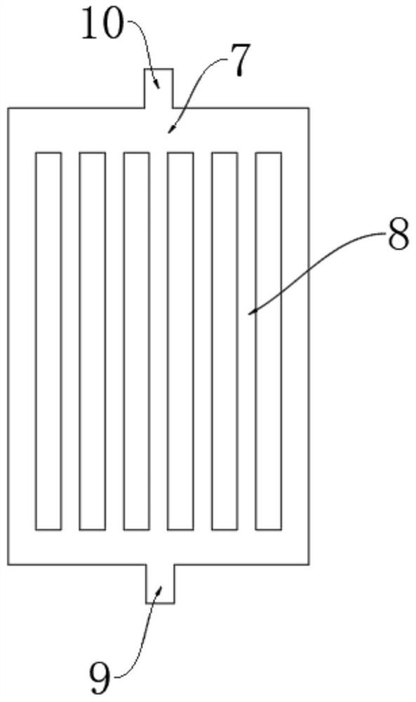
[0051] Embodiment one: according to image 3 As shown, the two liquid collecting pipes are respectively connected with the upper and lower ends of the branch pipe 8, the top of the middle section of the upper liquid collecting pipe is provided with a flow channel inlet 10, the bottom of the middle section of the liquid collecting pipe at the lower part is provided with a flow channel outlet 9, and the branch pipe 8 is Several dispensing tubes are arranged side by side, and the length of several dispensing tubes is the same; and the distance between two adjacent dispensing tubes is the same, and the diameter of both ends of each dispensing tube is larger than the diameter of the middle part of the dispensing tube . The liquid collecting pipe is a horizontal flow channel and the liquid distribution pipe is a vertical flow channel; the liquid enters the liquid collecting pipe from the flow channel inlet 10, and then flows into each liquid distribution pipe evenly

[0052] Furthe...

Embodiment 2

[0053] Embodiment two: according to Figure 5 As shown, the two liquid collecting pipes are respectively connected with the upper and lower ends of the branch pipe 8, one end of the upper liquid collecting pipe is provided with a flow channel inlet 10, and one end of the lower liquid collecting pipe is provided with a flow channel outlet 9 and a flow channel inlet 10 Arranged on the same side as the outlet 9 of the flow channel; the branch pipe 8 is formed by arranging a number of liquid pipes side by side, and the lengths of the several liquid pipes are the same; and the distance between two adjacent liquid pipes is the same, the The diameter gradually decreases in the same horizontal direction. The dispensing tubes near the channel outlet 9 and the channel inlet 10 are the smallest diameter dispensing tubes. The liquid collection pipe is a horizontal channel and the liquid distribution pipe is a longitudinal flow channel; the liquid enters the liquid collection pipe from th...

Embodiment 3

[0054] Embodiment three, according to Figure 4 As shown, the two liquid collecting pipes are respectively connected with the upper and lower ends of the branch pipe 8, one end of the upper liquid collecting pipe is provided with a flow channel inlet 10, and the other end of the lower liquid collecting pipe is provided with a flow channel outlet 9, and the flow channel outlet 9 is arranged away from the inlet 10 of the runner. The branch pipe 8 is formed by arranging several liquid pipes side by side, and the lengths of the several liquid pipes are the same; and the distance and diameter between two adjacent liquid pipes are the same. The liquid collection pipe is a horizontal channel and the liquid distribution pipe is a longitudinal flow channel; the liquid enters the liquid collection pipe from the inlet 10 of the flow channel, and the liquid distribution pipes are parallel to each other, and the distance between two adjacent liquid distribution pipes same. This structure...


PUM


Abstract

The invention discloses a photovoltaic and photo-thermal integrated building material photovoltaic module, and relates to the technical field of solar cells. The assembly comprises a photovoltaic panel layer, and the photovoltaic panel layer is sequentially provided with a glass plate, a battery piece group and a back plate from top to bottom; one side of the battery piece group is connected with one side of the glass plate, the other side of the battery piece group is connected with one side of the back plate, and the battery piece group absorbs illumination to generate electric energy; the back plate is an aluminized zinc plate; the assembly further comprises a photo-thermal element detachably connected with the other side of the back plate; the photo-thermal element comprises a high heat conduction layer and a heat insulation layer, the two sides of the high heat conduction layer are connected with the other side of the back plate and the heat insulation layer respectively, and a high polymer material heat collection plate is arranged in the high heat conduction layer; and the polymer material heat collection plate comprises a plate body and a fluid channel formed in the plate body, and the fluid channel is provided with a flow channel inlet and a flow channel outlet. The photovoltaic and photo-thermal integrated assembly is compact in structure and easy and convenient to manufacture and install.

Description

technical field [0001] The invention relates to the technical field of solar cells, in particular to a building material photovoltaic module integrating photovoltaic, light and heat. Background technique [0002] The burning of fossil fuels, coal, and other non-renewable resources to generate electricity produces harmful carbon emissions that are released into the atmosphere. These carbon emissions have a negative impact on the environment, greatly increasing global warming and causing natural disasters. Therefore, it is necessary to reduce carbon emissions by using more renewable energy sources such as wind and solar to generate electricity. [0003] People and businesses have been drawn to the virtues of solar energy, which is not only good for the environment but also generates its own electricity. Solar energy, or photovoltaics, has been used for decades by harnessing sunlight to generate usable electricity. In actual photovoltaic applications, it is found that under ...

Claims


Application Information

Patent Timeline
Patent Type & Authority Applications(China)
IPC IPC(8): H02S40/44H02S20/23H02S20/26H01L31/049H01L31/048H01L31/0224
CPCH02S40/44H02S20/23H02S20/26H01L31/049H01L31/0481H01L31/022425Y02E10/50Y02E10/60Y02B10/10
Inventor 胡长兴虞效益李威
Owner 浙大宁波理工学院
Why Eureka
Try Eureka