Chloroform rectification device and rectification process

A chloroform and rectification technology, applied in fractionation, distillation separation, chemical industry and other directions, can solve the problem of frequent blockage of the reboiler of the rectification tower, reduce the demand for heat source quality, save the production cost of enterprises, and avoid the effect of coking

Pending Publication Date: 2021-12-21
聊城鲁西氯甲烷化工有限公司
View PDF7 Cites 0 Cited by
  • Summary
  • Abstract
  • Description
  • Claims
  • Application Information

AI Technical Summary

Problems solved by technology

[0005] In order to solve the deficiencies of the prior art, the purpose of the present invention is to provide a chloroform rectification device and rectification process, which can solve the problem of frequent blockage of the rectification tower reboiler, thereby realizing the long-term operation of the chloroform rectification tower

Method used


Image

  • Chloroform rectification device and rectification process
  • Chloroform rectification device and rectification process
  • Chloroform rectification device and rectification process

Examples


Embodiment 1

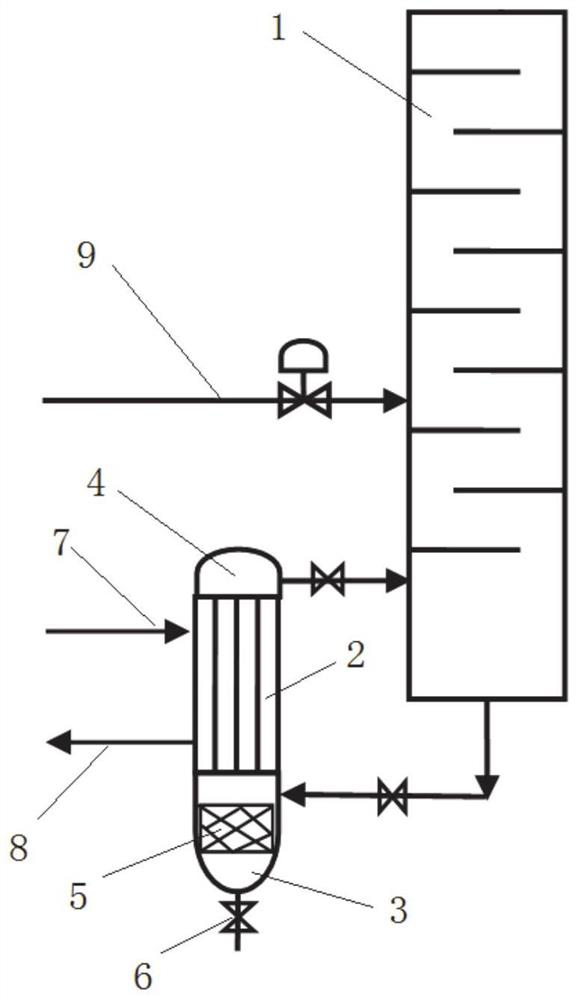
[0050] A chloroform distillation unit, such as figure 1 As shown, a chloroform rectification tower 1 is included, and two parallel reboilers 2 are arranged at the bottom of the chloroform rectification tower 1 .

[0051] The reboiler 2 is a tube-and-tube heat exchanger, and the reboiler 2 is arranged vertically. The length of the lower head 3 of the reboiler 2 in the axial direction of the reboiler 2 is greater than the length of a common head (such as the upper head 4 of the reboiler 2 ), so that a settling zone 5 is formed in the lower head 3 . The bottom head 3 is provided with the tower kettle material inlet and the sewage outlet, and the sewage outlet is provided with a sewage valve 6 . The material inlet of the tower kettle is set above the settling area 5, and the sewage outlet is set below the settling area 5 (that is, the bottom of the lower head 3). The upper head 4 is provided with a tower kettle material outlet.

[0052] The upper heat source inlet 7 of the shel...

Embodiment 2

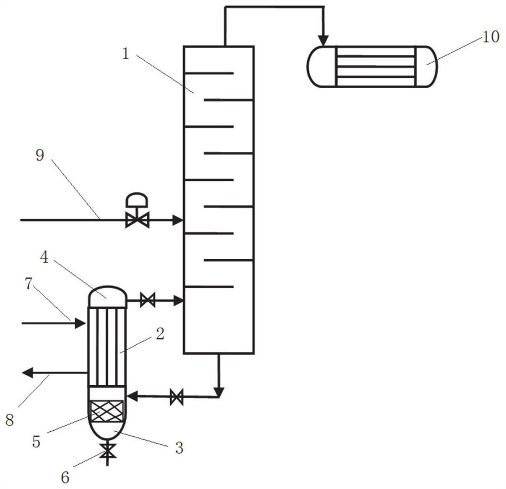
[0059] This embodiment is the same as Embodiment 1, the difference is that, as figure 2 As shown, a top condenser 10 is arranged at the top of the chloroform rectification column 1 .

Embodiment 3

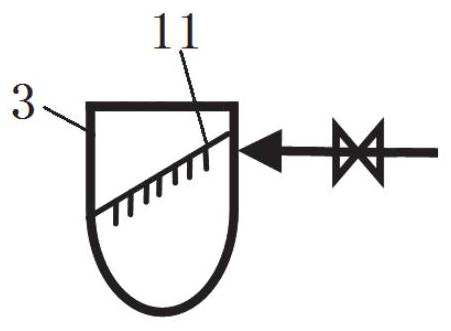
[0061] This embodiment is the same as Embodiment 2, the difference is that, as image 3 As shown, the baffle plate 11 that can be detachably installed in the settling area, the baffle plate 11 is inclined, and one side of the baffle plate 11 is arranged on the top of the material inlet of the reboiler 2 tower kettle (and the junction is connected with the material inlet of the tower kettle Located on the same side of the lower head 3 of the reboiler 2), the other side of the baffle plate 11 is arranged below the material inlet of the reboiler 2 tower kettle (and the connection is located at the lower seal of the reboiler 2 where the material inlet of the tower kettle is located) Opposite side of head 3 side). Setting baffles can further reduce the flow velocity of the material after entering the settling zone, which is conducive to the settlement of large particles of impurities at the bottom of the settling zone. The baffle is detachable and easy to clean, reducing the maint...


PUM


Abstract

The invention belongs to the technical field of energy conservation and environmental protection, and relates to an energy-saving heat exchange device in a chloroform rectification process, in particular to a chloroform rectification device and a rectification process. The chloroform rectification device comprises a chloroform rectifying tower, the bottom of the chloroform rectifying tower is provided with at least two reboilers, the reboilers are vertically arranged, the reboilers are tube type heat exchangers, lower end sockets of the reboilers are provided with settlement areas, the settlement areas are spaces capable of carrying out settlement, shell pass inlets of the reboilers are connected with a steam source, and the steam of the steam source is lower than 0.4 MPa. The problem of frequent blockage of the reboiler of the rectifying tower can be solved, so that long-period operation of the chloroform rectifying tower is realized, meanwhile, the energy consumption can be greatly reduced, and the production cost is saved.

Description

technical field [0001] The invention belongs to the technical field of energy saving and environmental protection, and relates to an energy-saving heat exchange device in a chloroform rectification process, in particular to a chloroform rectification device and a rectification process. Background technique [0002] The information disclosed in this background section is only intended to increase the understanding of the general background of the present invention, and is not necessarily taken as an acknowledgment or any form of suggestion that the information constitutes the prior art already known to those skilled in the art. [0003] Methane chloride is the general term for monochloromethane (also known as chloromethane), dichloromethane, chloroform (also known as chloroform) and carbon tetrachloride (also known as tetrachloromethane), which is second only to vinyl chloride in organic products. The bulk chlorine products are important chemical raw materials and organic sol...

Claims


Application Information

Patent Timeline
Patent Type & Authority Applications(China)
IPC IPC(8): B01D3/32C07C17/383C07C19/04
CPCB01D3/322C07C17/383C07C19/04Y02P20/50Y02P20/10
Inventor 马臣信肖军昌于百胜孙久栋闫家战徐迪张红杰王海霞崔心健
Owner 聊城鲁西氯甲烷化工有限公司
Why Eureka
Try Eureka