Isoparametric transformation mixed structure of bionic bone scaffold and 3D printing method thereof

A 3D printing and hybrid structure technology, applied in 3D object support structures, bone implants, geometric CAD, etc., can solve the problem that the bionic scaffold cannot meet the pore structure, mechanical properties and materials at the same time, so as to prevent the decline of mechanical properties, The effect of high Young's modulus

Active Publication Date: 2021-12-21
WUHAN UNIV OF SCI & TECH
View PDF10 Cites 0 Cited by
  • Summary
  • Abstract
  • Description
  • Claims
  • Application Information

AI Technical Summary

Problems solved by technology

Existing research on bionic scaffolds cannot meet the requirements of pore structure, mechanical properties and materials at the same time

Method used


Image

  • Isoparametric transformation mixed structure of bionic bone scaffold and 3D printing method thereof
  • Isoparametric transformation mixed structure of bionic bone scaffold and 3D printing method thereof
  • Isoparametric transformation mixed structure of bionic bone scaffold and 3D printing method thereof

Examples


Embodiment 1

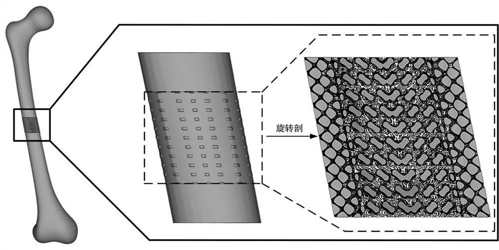
[0081] Such as figure 1 As shown, a bionic bone scaffold designed for this embodiment can well match the shape and mechanical properties of the femoral shaft. The general process of constructing the bionic bone scaffold is as follows:

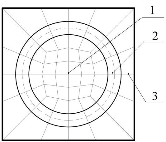
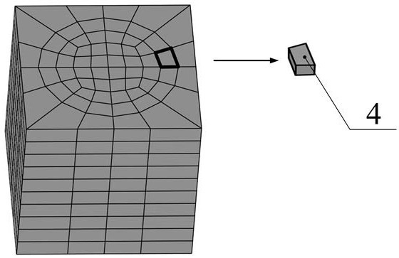
[0082] First, generate a cube model with a side length of 25mm. Then, pass the cube model through figure 2 and image 3 The partitioning method shown is partitioned into a series of subspaces 4 . Next, the minimal curved surface structure cell 5 whose space is a regular cube is carried out according to the space node parameters of the subspace 4 as follows Figure 5 As shown in the linear isoparametric transformation, the transformed minimum surface structure cell 7 is obtained, and the transformed minimum surface structure cell 7 is filled in all the divided subspaces 4, and the following is obtained: Figure 6 The biomimetic bone scaffold shown. Finally, through the secondary isoparametric transformation, the shape of the bionic bone ...

Embodiment 2

[0120] Further, as figure 2 As shown, the bionic bone scaffold is divided into three layers from inside to outside, which are inner layer 1, transition layer 2 and outer layer 3 respectively. The inner layer 1 has a diameter of 15mm and a porosity of 70%, simulating cancellous bone; the transition layer 2 has an inner diameter of 15mm and an outer diameter of 20mm, and the porosity decreases linearly from 70% to 10%; the outer layer 3 has an inner diameter of 20mm, and the outer The side length is 25mm, and the porosity is 10%, simulating dense bone. Such as Figure 15 The inner layer 1 structure adopts the Network-type Diamond structure 10, the outer layer 3 adopts the Network-type Primitive-Opt structure 11, the inner layer adopts the transition layer 2 and uses the Sigmond function to fuse the two structures of the inner layer 1 and the outer layer 3, and the fusion boundary line is figure 2 The dotted circle in the dotted line has a radius of 8.75mm.

[0121] The form...


PUM

PropertyMeasurementUnit
yield strengthaaaaaaaaaa
modulusaaaaaaaaaa

Abstract

The invention belongs to the field of additive manufacturing and bionic structure design, and discloses an isoparametric transformation mixed structure of a bionic bone scaffold and a 3D printing method thereof. The bionic bone scaffold is composed of an inner layer, a transition layer and an outer layer, wherein the outer layer uses an extremely small curved surface with main tensile deformation to simulate a compact bone; the inner layer uses an extremely small curved surface with a high specific surface area to simulate cancellous bone; the transition layer combines the two the inner layer and the outer layer through a Sigmond function, and the overall structure simulates the appearance of the human skeleton through isoparametric transformation. The bionic bone scaffold can simulate the appearance, pore characteristics, Young's modulus and completely communicated pore structures of human bones, can be matched with damaged areas of the bones, can realize body fluid transportation, can meet the requirements of mechanical properties and bone ingrowth, and can be used for treating bone defects.

Description

technical field [0001] The invention relates to the fields of additive manufacturing and bionic structure design, in particular to an isoparametric transformation hybrid structure of a bionic bone bracket and a 3D printing method thereof. Background technique [0002] Bone is an important part of the human body, which supports and protects the human body. However, every year, there are a large number of patients with bone defects caused by trauma, craniotomy, bone tumor resection, and bone deformity correction. Bone transplantation is required. repair. However, medical bone resources are scarce, and it is difficult to meet medical needs in the face of a large number of bone defect patients every year. In order to solve the problem of insufficient bone source, many researchers hope to fill the bone defect by constructing a suitable bionic scaffold in vitro, so as to solve the problem of insufficient bone source. [0003] In order to ensure high cell activity of bone cells i...

Claims


Application Information

Patent Timeline
Patent Type & Authority Applications(China)
IPC IPC(8): G06F30/10G06F30/23A61F2/28B29C64/386B29C64/118B33Y50/00B33Y10/00B33Y80/00G06F113/10G06F119/14B29K71/00
CPCG06F30/10G06F30/23A61F2/28B29C64/386B29C64/118B33Y50/00B33Y10/00B33Y80/00
Inventor 林昕朱锟鹏杨博汪朝晖周艳郑祖嘉
Owner WUHAN UNIV OF SCI & TECH
Why Eureka
Try Eureka