
Production equipment, production system and production process of glass fiber composite filter material

A glass fiber composite and production equipment technology, applied in the direction of synthetic cellulose/non-cellulose material pulp/paper, filter paper, filtration separation, etc., can solve the problems of reducing filter resistance, glass fiber filter material cracking, and yield reduction, etc. problems, achieve the effect of reducing energy consumption, reducing the pressure drop of filter media and prolonging the service life

Pending Publication Date: 2021-12-24
NANJING FIBERGLASS RES & DESIGN INST CO LTD
View PDF2 Cites 0 Cited by
  • Summary
  • Abstract
  • Description
  • Claims
  • Application Information

AI Technical Summary

Problems solved by technology

[0008] Therefore, the technical problem to be solved by the present invention is to solve the defect that the glass fiber composite filter material produced in the prior art cannot reduce the filtration resistance of the filter material on the basis of ensuring a high tensile strength, thereby providing a glass fiber Production equipment, production system and production process of composite filter material
[0009] Another technical problem solved by the present invention is that when the surface of the glass fiber filter material is coated with an adhesive, the glass fiber filter material is prone to cracking and wrinkles, resulting in damage to the filter material and a decrease in yield.

Method used


Image

  • Production equipment, production system and production process of glass fiber composite filter material
  • Production equipment, production system and production process of glass fiber composite filter material
  • Production equipment, production system and production process of glass fiber composite filter material

Examples


Embodiment 1

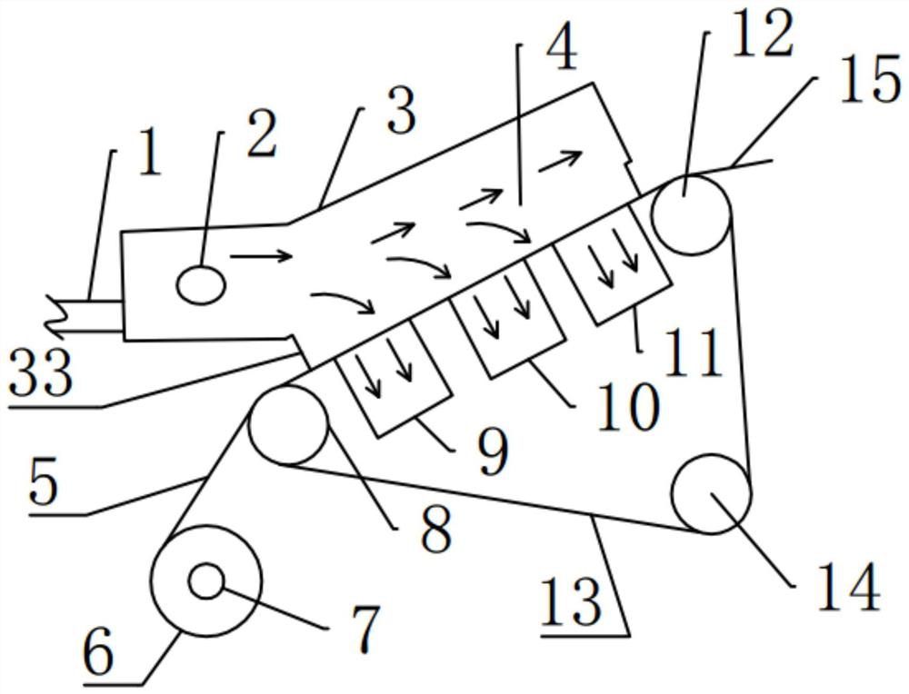
[0060] Such as figure 1 The production equipment of the shown glass fiber composite filter material comprises a headbox 3, a forming wire 13, a first unwinding roller 7, a first dewatering device and a driving mechanism, wherein the headbox 3 is used to provide a glass fiber filter for preparation. The fiber slurry required by the material.

[0061] One side of the headbox 3 is provided with a slurry inlet, and the bottom of the headbox is provided with a slurry outlet, and the headbox 3 is located at the slurry inlet and is connected with a slurry delivery pipeline 1, and the slurry delivery pipeline 1 is also It is connected with a slurry pump, and the fiber slurry flows into the headbox 3 through the slurry delivery pipeline 1 through the slurry pump.

[0062] The first dehydration device is closely attached to the lower surface of the forming net 13, and the forming net 13 is communicated with the slurry outlet, and the first dehydration device is communicated with the sl...

Embodiment 2

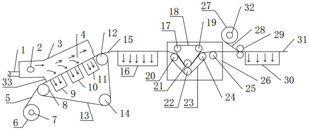
[0074] Such as figure 2 The production system of the glass fiber composite filter material shown, in addition to the production equipment of the glass fiber composite filter material in Example 1, also includes an impregnation device.

[0075] The dipping device of the present embodiment is a dipping machine 26, comprising a dipping tank for impregnating the glass fiber filter material and a clamping device arranged in the dipping tank, the clamping device includes an upper clamping net 18 and a lower clamping net 23, respectively surrounding On at least two impregnation driving rollers, there are three impregnation driving rollers in this embodiment, and the upper clamping net 18 and the lower clamping net 23 are arranged in an inverted triangle structure, which are respectively the fourth driving roller 17 and the fifth driving roller. 19, the sixth driving roller 20, the seventh driving roller 21, the eighth driving roller 22 and the ninth driving roller 24, there is a gap...

Embodiment 3

[0080] The present embodiment provides a kind of production technology of glass fiber composite filter material, adopts the production system of glass fiber composite filter material that embodiment 2 provides to make, comprises the following steps:

[0081] (1) Dispersing glass microfibers with a degree of beating of 39° in water, adjusting the pH value of the slurry to 3 using sulfuric acid to obtain a fiber slurry with a mass percentage of glass microfibers of 0.5%;

[0082] (2) Start the driving motor and the vacuuming device so that the first driving roller 8, the second driving roller 12 and the third driving roller 14 rotate, and simultaneously drive the polyester forming net 13 to rotate; drive the first unwinding roller 7 to rotate, and Non-woven fabric (air permeability of 1000mm / s, 50g / m 2 ) to the forming net 13, the non-woven fabric is flattened on the forming net 13, and advances with the rotation of the forming net 13; the slurry pump is started to make the fibe...


PUM

PropertyMeasurementUnit
Thicknessaaaaaaaaaa

Abstract

The invention belongs to production equipment of filter materials, and particularly relates to production equipment, a production system and a production process of a glass fiber composite filter material. The production equipment of the glass fiber composite filter material comprises a headbox provided with a slurry inlet and a slurry outlet, a forming net communicated with the slurry outlet, a driving mechanism used for driving the forming net to circularly pass through the slurry outlet, a first unwinding roller used for conveying a protective layer between the headbox and the forming net, and a first dehydration device communicated with the slurry outlet through the forming net. Through the production equipment, the double-layer glass fiber composite filter material can be formed without adding a hot melt adhesive, and the double-layer glass fiber composite filter material has higher tensile strength, so that on the basis of ensuring higher tensile strength, the filtering resistance and the pressure drop of the filter material are obviously reduced, the air permeability of the glass fiber filter material is improved, then the service life is facilitated to be prolonged, and the energy consumption is reduced.

Description

technical field [0001] The invention belongs to production equipment of filter materials, and in particular relates to production equipment, a production system and a production process of glass fiber composite filter materials. Background technique [0002] With the development of society and the improvement of people's living standards, people's requirements for environmental quality are getting higher and higher. Countries all over the world pay more and more attention to the development and application of dust removal technology and equipment. At present, dust removal devices mostly use bag filter and electrostatic precipitator. The key of bag filter is filter material. Glass fiber filter material is widely used because of its high temperature resistance, corrosion resistance, smooth surface, dust peeling and good dimensional stability. It is used in air and liquid filtration in many fields. The production process of glass fiber filter material is similar to that of spe...

Claims


Application Information

Patent Timeline
IPC IPC(8): D21F11/02D21F9/02D21F1/02D21H13/40D21H23/32D21H21/16B32B38/08B32B37/12B32B38/16D21H27/08
CPCD21F11/02D21F9/02D21F1/02D21H13/40D21H23/32D21H21/16B32B38/08B32B37/12B32B38/164D21H27/08
Inventor 吴耀春杨超石玉强钱慧李建姚嘉兰
Owner NANJING FIBERGLASS RES & DESIGN INST CO LTD
Learn More