Descending type suspended casting hanging basket and construction method thereof

A hanging and cantilever truss technology, applied in the erection/assembly of bridges, bridges, buildings, etc., can solve the problems of increased workload, high safety risk, repeated adjustment, etc., to reduce personnel requirements, high surface flatness, safety and reliability. The effect of support

Pending Publication Date: 2021-12-31
CHINA CONSTR THIRD ENG BUREAU GRP CO LTD
View PDF4 Cites 0 Cited by
  • Summary
  • Abstract
  • Description
  • Claims
  • Application Information

AI Technical Summary

Problems solved by technology

[0003] 1) The bridge deck is messy, the line of sight is poor, and there are many restrictions on the working surface. The cantilever structures of the existing hanging baskets on the market usually include diamond trusses, triangular trusses, steel plate girders, Bailey beams, bowstring structures, etc. The common feature of the above structures is that they all need to be installed A large number of temporary steel structures are arranged on the bridge surface to form a strong enough cantilever bearing system. Usually, the higher the height of the main cantilever bearing structure formed by the same structure and the same material, the stronger the bending resistance of the cantilever. Therefore, the on-site The bridge deck is equipped with a relatively high steel frame (generally greater than 4m); in addition, the connecting system between the frames, the running device of the entire hanging basket, and the anchoring device are all arranged on the bridge deck, plus The exposed steel bars reserved on the bridge deck leave relatively limited space for other operations, and the entire bridge deck is often disorganized, making it difficult to meet the requirements of civilized construction
[0004] 2) The running conditions of the bridge deck are relatively poor - the flatness of the cast-in-place bridge deck is

Method used


Image

  • Descending type suspended casting hanging basket and construction method thereof
  • Descending type suspended casting hanging basket and construction method thereof
  • Descending type suspended casting hanging basket and construction method thereof

Examples


Embodiment Construction

[0035] The present invention will be further described below with reference to the accompanying drawings and examples.

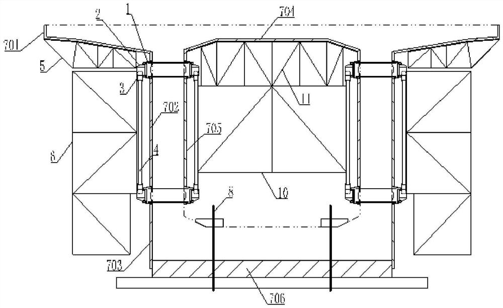
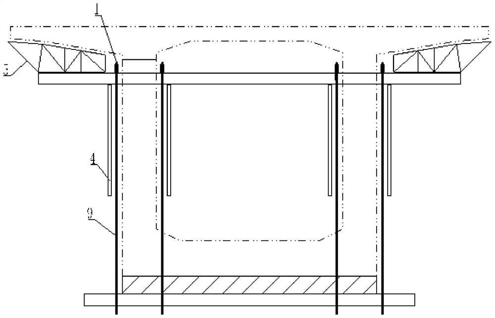
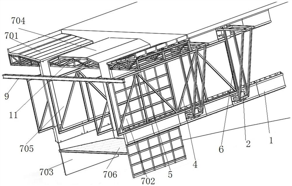
[0036] like Figure 1 to 4As shown in a downlink of Formula Suspended Casting Basket, comprising a template bearing parts 1, 2 corbels support the running, adjusting cylinder 3, cantilevered truss 4, mold flange 5, the bracket 6 attached to the side, the template system 7, after hanging hanging system 8, 9 before the hanging system, the tank holder 10 and the top mold 11; box 1 adhered webs template has been poured fixed bearing parts of the upper and lower inner and outer sides, the inner side surface of the template bearing parts 1 as a template, with the outer side surface of the running rail, with the support 2 fitted corbel traveling traveling within the track, the inner and outer sides positioned Box cantilever truss web support 4 and connected to upper and lower sides of the supporting cylinder by adjusting the vertical side 3 traveling corbel 2, each side...


PUM


Abstract

The invention discloses a descending type suspended pouring hanging basket and a construction method thereof. The hanging basket comprises a formwork force bearing piece (1), a bearing walking bracket (2), an adjusting oil cylinder (3), a cantilever truss (4), a flange formwork (5), a side attachment support (6), a formwork system (7), a rear hanging system (8), a front hanging system (9), an in-box support (10) and a top formwork (11). The main stress structure and the working platform are moved downwards to the position below the bridge floor, the space of the bridge floor is released, the construction risk is reduced, the walking working face is moved to the position of the web, automatic walking can be achieved, elevation adjustment of the cantilever structure can be achieved, the overall structure is stable, forward moving is convenient, and safety and reliability are achieved.

Description

Technical field [0001] The present invention is in the field of bridge construction, in particular to a downlink of formula Suspension Cast Cradle and construction method. Background technique [0002] The following defects existing Cradle bridge construction: [0003] 1) deck clutter, the difference between the line of sight, multiple restriction face - Basket existing on the market usually have a cantilever structure TRUSS, triangular truss, steel girder, Bailey beam, bow structure, a common feature in the above structure are required large temporary steel bridge arrangement formed on a sufficiently strong force boom system, under normal circumstances, the same kind of structure, the same material forming the main boom force structure height the higher, the stronger the cantilever bending resistance, and therefore, in the field deck disposed relatively high steel frame body (generally greater than 4M); in addition, the connecting lines between the frame body, the entire running...

Claims


Application Information

Patent Timeline
IPC IPC(8): E01D21/10
CPCE01D21/10
Inventor 王辉王开强陈波方小林陈百奔张宇王汉章
Owner CHINA CONSTR THIRD ENG BUREAU GRP CO LTD
Why Eureka
Try Eureka