
Blow tank odor treatment system and treatment method

A technology of odor and pot odor, which is applied in the field of pollution control, can solve problems such as odor pollution and exhaustion, and achieve the effects of saving investment costs, stabilizing temperature and gas volume, and low investment

Pending Publication Date: 2022-01-07
四川永丰浆纸股份有限公司
View PDF5 Cites 0 Cited by
  • Summary
  • Abstract
  • Description
  • Claims
  • Application Information

AI Technical Summary

Problems solved by technology

[0003] Aiming at the defects in the above-mentioned prior art, the present invention provides a system and method for controlling the odor of the blowing pot, so as to solve the problem of the large amount of exhaust gas in the gap vertical pot of the pulp mill, which is difficult to control when the cooking spraying pot is put into the pot, which leads to the direct discharge of the stench. The problem of polluted air

Method used


Image

  • Blow tank odor treatment system and treatment method
  • Blow tank odor treatment system and treatment method
  • Blow tank odor treatment system and treatment method

Examples


Embodiment 1

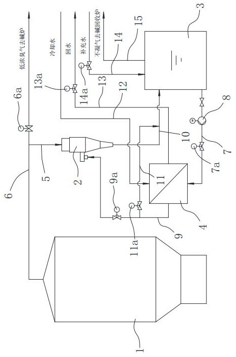
[0034] Such as figure 1 As shown, the application embodiment of the present invention provides a spray pot odor control system, including a spray pot 1, a condensation injector 2, a sewage hot water tank 3, a heat exchanger 4, and the like.

[0035] The outlet on the spray pot 1 top is connected with an alkali furnace through a low-concentration odor pipe 6, and the low-concentration odor pipe 6 is provided with a bypass valve 6a.

[0036] The upper end of the condensing ejector 2 has an air inlet, and the low-concentration odor pipe 6 between the spray pot 1 and the bypass valve 6a is connected to the air inlet on the upper end of the condensing ejector 2 through the first pipeline 5 .

[0037] The outlet of the sewage hot water tank 3 is connected to the inlet of the heat exchanger 4 through the second pipeline 7 , and the outlet of the heat exchanger 4 is connected to the water inlet of the condensation injector 2 through the third pipeline 9 .

[0038] A jet pump 8 and a ...

Embodiment 2

[0043] Existing ZJF jet condenser (such as Figure 4 As shown), the orifice plate 100 on the top is prone to fouling and blockage, resulting in a drop in the pressure of the condensed water and a decrease in the odor absorption capacity, which eventually leads to the direct discharge of the odor and pollutes the air.

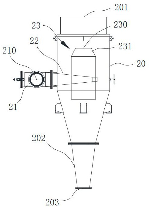
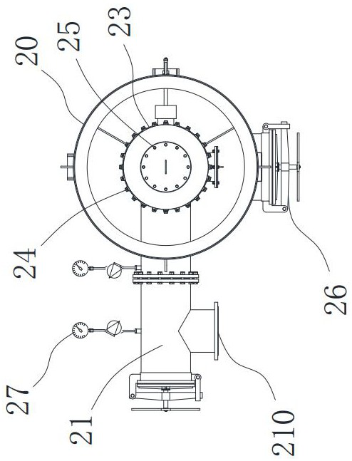
[0044] Such as Figure 1 ~ Figure 3 As shown, the application embodiment of the present invention provides a spray pot odor control system, including a spray pot 1, a condensation injector 2, a sewage hot water tank 3, a heat exchanger 4, and the like.

[0045] The outlet on the spray pot 1 top is connected with an alkali furnace through a low-concentration odor pipe 6, and the low-concentration odor pipe 6 is provided with a bypass valve 6a. The upper end of the condensing injector 2 has an air inlet 201, and the low-concentration odor pipe 6 between the spray pot 1 and the bypass valve 6a is connected to the air inlet 201 at the upper end of the condensing in...

Embodiment 3

[0054] Such as Figure 1 ~ Figure 3 As shown, the embodiment of the application of the present invention provides a method for controlling the odor of the spray pot, which is carried out by using the system described in Embodiment 1 and / or Embodiment 2, including the following steps:

[0055] In step S1, before the coarse slurry enters the spray pot 1, water is supplied to the condensing injector 2 for a certain time in advance, so that a slight negative pressure is established in the exhaust pipe.

[0056] When the cooking pot enters the discharge program, the DCS system automatically starts the jet pump 8 60 seconds in advance, opens the second control valve 9a, closes the third control valve 11a to supply water to the condensing jet 2, and the jet water passes through the heat exchanger 4 to exchange heat with The pressure greater than or equal to 0.05MPa supplies water to the condensing injector 2, so that the exhaust pipe establishes a slight negative pressure. The verti...


PUM


Abstract

The invention provides a blow tank odor treatment system and a treatment method, and aims to solve the technical problem of air pollution caused by direct emission of odor due to difficulty in treatment caused by large gas displacement during blowing of the blow tank. The treatment system comprises a condensation ejector connected with the blow tank and a dirty hot water tank connected with a water inlet of the condensation ejector, wherein an outlet of the dirty hot water tank is connected with a water inlet in one side of the condensation ejector after passing through a heat exchanger. The treatment method is carried out through the system and comprises the steps: S1, before blowing of the blow tank, water is supplied to the condensation ejector in advance for a certain time, and micro-negative pressure is established in the exhaust pipe; and S2, after the pressure of the system is stable, slurry pumping is started, water is continuously supplied to the condensation ejector, and water flow enters the condensation ejector at a certain pressure and temperature after heat exchange and is sprayed out in an atomized foam and high-speed jet flow mode. The problem that gas displacement is large and difficult to treat can be effectively solved, and it is avoided that odor is directly exhausted to pollute air.

Description

technical field [0001] The invention relates to the technical field of pollution control, in particular to a control system and a control method for spraying pot odor. Background technique [0002] Since the traditional intermittent vertical pot cooking process in the pulp mill adopts spraying with pressure (that is, hot spraying process, the temperature of the pot is above 100°C), there is a large amount of high-temperature odor in the coarse pulp when the pot is put. The existing process for treating and emitting odor is only suitable for 30,000 m 3 The amount of odor within / h, for more than 30,000 m 3 The amount of odor per hour cannot achieve a good treatment effect, and there is still a large amount of odor directly discharged into the atmosphere, polluting the air. Contents of the invention [0003] Aiming at the defects in the above-mentioned prior art, the present invention provides a system and method for controlling the odor of the blowing pot, so as to solve ...

Claims


Application Information

Patent Timeline
Patent Type & Authority Applications(China)
IPC IPC(8): B01D53/18B01D53/14F23G7/06F28D21/00D21C7/00
CPCB01D53/18B01D53/185B01D53/14F23G7/06F28D21/0003D21C7/00F23G2209/14Y02P70/10
Inventor 李乾金朱君陈泗均丁长劲涂建华
Owner 四川永丰浆纸股份有限公司
Learn More