Denitration device for flue gas from cement kiln and use method of denitration device

A flue gas and denitrification technology, applied in separation methods, chemical instruments and methods, dispersed particle separation, etc., can solve the problems of decreased denitration efficiency, failure to meet emission standards, and high operating costs, reducing the risk of poisoning and deactivation, The effect of reducing the denitration operating cost and improving the catalytic activity

Active Publication Date: 2022-01-11
山东东源新材料科技有限公司
View PDF10 Cites 0 Cited by
  • Summary
  • Abstract
  • Description
  • Claims
  • Application Information

AI Technical Summary

Problems solved by technology

[0003] SNCR technology has low investment, low operating cost, simple system, and wide application range, but its denitrification efficiency is low, only 30%-50%, far from meeting the emission standards
[0004] The operation cost of SCR technology is high, and the denitrification efficiency can reach more than 95% at the flue gas temperature of about 300°C. Unequal heavy metals, so it is easy to cause catalyst blockage, wear, poisoning and failure. It must be dedusted by a low-temperature dust collector and then denitrated by SCR technology. After low-temperature dust removal, the temperature of the flue gas will drop below 150 ° C, which will affect the SCR reaction. The activity of the catalyst in the device leads to a decrease in the denitrification efficiency. To improve the denitrification efficiency, it is necessary to reheat the low-temperature flue gas, which increases energy consumption and further increases the already high operating cost.

Method used


Image

  • Denitration device for flue gas from cement kiln and use method of denitration device
  • Denitration device for flue gas from cement kiln and use method of denitration device
  • Denitration device for flue gas from cement kiln and use method of denitration device

Examples


specific Embodiment approach

[0042] It should be noted that the structures, proportions, sizes, etc. shown in the drawings attached to this specification are only used to match the content disclosed in the specification, for those who are familiar with this technology to understand and read, and are not used to limit the implementation of the present invention Any modification of structure, change of proportional relationship or adjustment of size shall fall within the range covered by the technical content disclosed in the present invention without affecting the effect and purpose of the present invention. within range.

[0043] At the same time, terms such as "upper", "lower", "left", "right", "middle" and "one" quoted in this specification are only for the convenience of description and are not used to limit this specification. The practicable scope of the invention and the change or adjustment of its relative relationship shall also be regarded as the practicable scope of the present invention without...

Embodiment 1

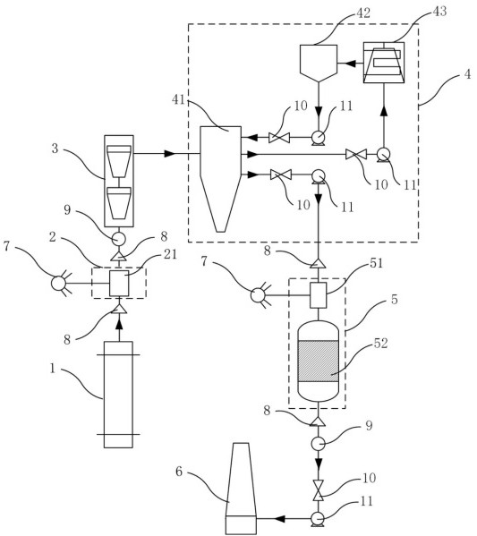
[0045] combined with figure 1 , This implementation provides a cement pit flue gas denitrification device, including a pit tail flue 1, an SNCR denitrification reaction unit 2, a preheater 3, a low-temperature dust removal unit 4, and an SCR denitrification reaction unit 5 connected sequentially along the flue gas direction and chimney 6, the SNCR denitration reaction unit 2 includes a first mixer 21; the SCR denitration reaction unit 5 includes a second mixer 51 and an SCR reactor 52 connected in sequence along the flue gas trend; Ammonia gas is injected into the first mixer 21 and the second mixer 51 ; the low-temperature dust removal unit 4 includes a low-temperature dust collector 42 .

[0046] In the above technical scheme, the combination of SNCR denitrification technology and SCR denitrification technology greatly reduces the denitrification operation cost. At the flue gas outlet near the pit tail flue 1, the SNCR denitrification reaction unit 2 is used for primary den...

Embodiment 2

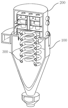
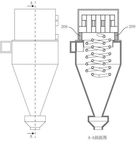
[0054] combined with Figure 2-5 , this embodiment provides a heat exchange device 41 used in Embodiment 1, the heat exchange device 41 sequentially includes a first heat exchange part 100 and a second heat exchange part 200 from bottom to top, the first heat exchange The high-temperature flue gas flowing out from the preheater 3 is passed into the part 100, the low-temperature flue gas flowing out from the low-temperature dust collector 42 is passed into the second heat exchange part 200, and the double-helix heat pipe 300 is fixed on the second Below the heat exchange part 200 and extending into the first heat exchange part 100 , the double helical heat pipe 300 includes a connected outer helical pipe 301 and an inner helical pipe 302 , and low-temperature flue gas flows through the double helical heat pipe 300 Then flow out to the second mixer 51.

[0055] In the above technical solution, the double-helix heat pipe 300 can prolong the residence time of the low-temperature ...


PUM


Abstract

The invention relates to the technical field of treatment of nitric oxide in flue gas from industrial kilns, in particular to a denitration device for flue gas from a cement kiln and a use method of the denitration device. The denitration device comprises a kiln tail flue, an SNCR denitration reaction unit, a preheater, a low-temperature dust removal unit, an SCR denitration reaction unit and a chimney which are sequentially connected along a flue gas flowing direction, wherein the SNCR denitration reaction unit comprises a first mixer; the SCR denitration reaction unit comprises a second mixer and an SCR reactor which are sequentially connected along the flue gas flowing direction; an ammonia gas source sprays ammonia gas into the first mixer and the second mixer respectively; and the low-temperature dust removal unit comprises a low-temperature dust remover. According to the denitration device for the flue gas from the cement kiln provided by the invention, denitration operation cost is reduced on the basis of ensuring denitration efficiency.

Description

technical field [0001] The invention relates to the technical field of industrial furnace flue gas nitrogen oxide treatment, in particular to a cement pit flue gas denitrification device and a use method thereof. Background technique [0002] Nitrogen oxides, as one of the main air pollutants, are the targets of the country's strict emission control after sulfur dioxide. At present, nitrogen oxide emissions from cement kilns account for about one-tenth of my country's total nitrogen oxide emissions, which need to be treated. Now the most widely used flue gas denitrification technologies are SCR technology and SNCR technology. [0003] SNCR technology has low investment, low operating cost, simple system and wide application range, but its denitrification efficiency is low, only 30%-50%, which is far from meeting the emission standards. [0004] The operation cost of SCR technology is high, and the denitrification efficiency can reach more than 95% at the flue gas temperatur...

Claims


Application Information

Patent Timeline
Patent Type & Authority Applications(China)
IPC IPC(8): B01D53/56B01D53/76B01D53/86B01D53/34B01D45/08
CPCB01D53/346B01D53/56B01D53/76B01D53/343B01D53/8625B01D45/08
Inventor 葛成敏周文韬刘易寒陈浩赵秀萍
Owner 山东东源新材料科技有限公司
Why Eureka
Try Eureka