
Graphene particle crushing process

A graphene and particle technology, applied in the field of graphene particle crushing technology, can solve the problems of low screening efficiency, low recovery efficiency, affecting the process, etc., and achieve the effects of high screening efficiency, saving electric energy, and preventing scattering

Inactive Publication Date: 2022-01-11
于秋菊
View PDF1 Cites 1 Cited by
  • Summary
  • Abstract
  • Description
  • Claims
  • Application Information

AI Technical Summary

Problems solved by technology

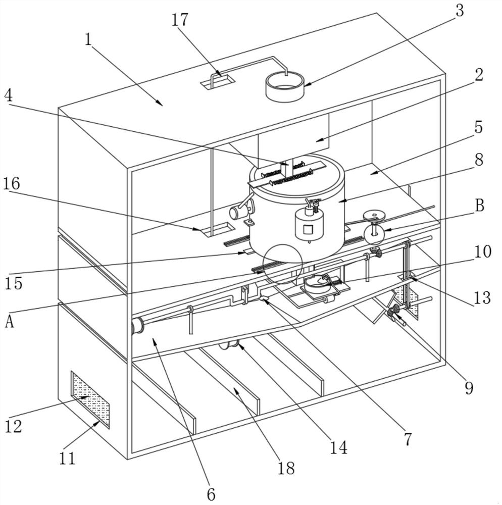
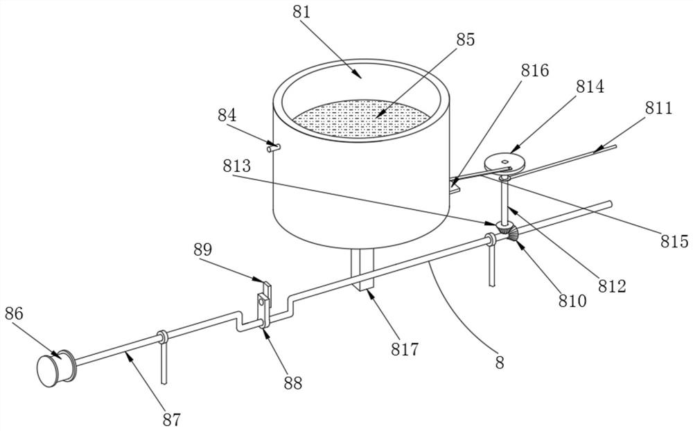
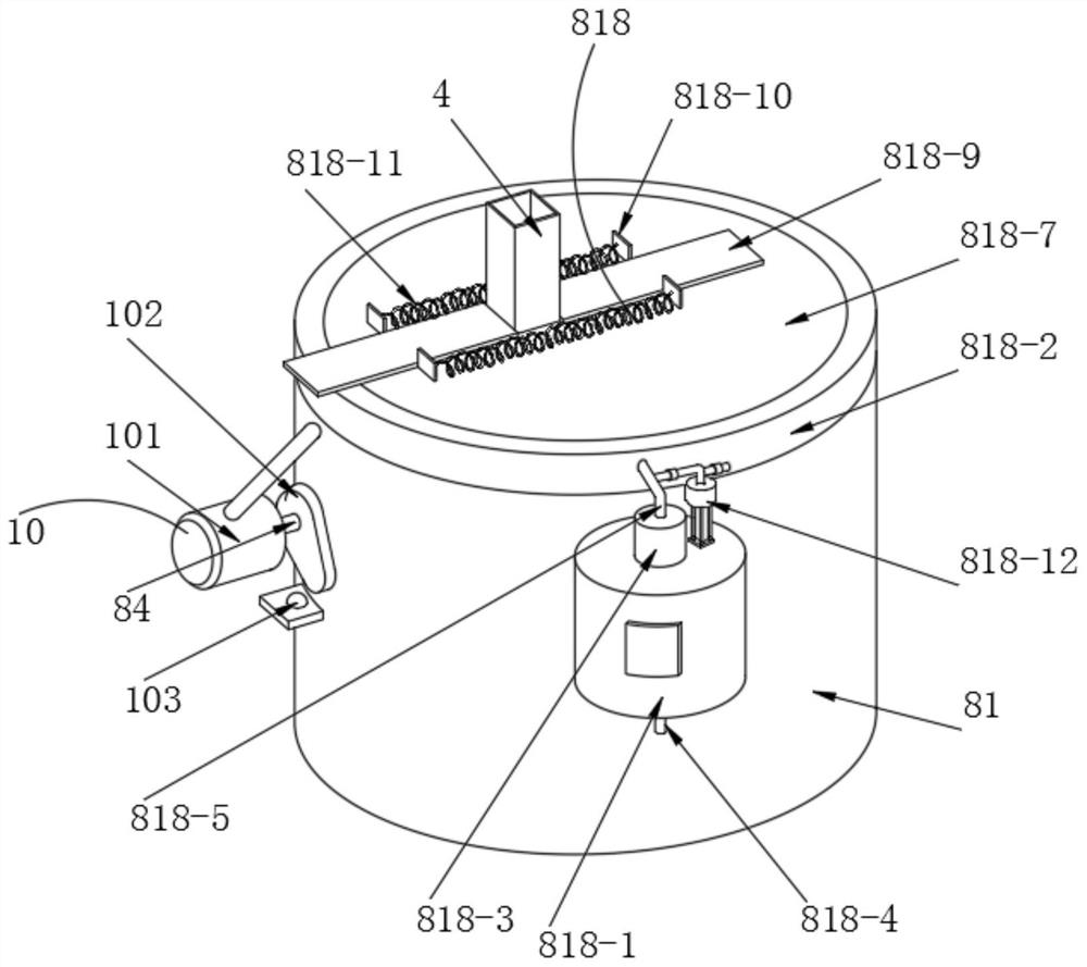
[0011] Aiming at the deficiencies of the prior art, the present invention provides a graphene particle crushing process, which solves the problem that the filter screen assembly driven by the drive assembly can only perform left and right unidirectional reciprocating movements, resulting in the large size of graphene after crushing in actual use. Particles will be blocked in the holes of the filter screen, causing the filter screen to be blocked. Only the trend of left and right movement cannot make the large graphene particles blocked in the holes discharged, which will cause the blockage of the filter screen and low screening efficiency; powdered graphene When sieving, a large amount of graphene dust will be generated, and these graphene dust will be scattered everywhere, which is very difficult to handle and will cause waste of raw materials; the pulverized graphene will still have insufficient pulverization, which is not enough It is convenient to recycle and pulverize the non-standard graphene particles on the filter, and it is generally recycled manually, and the recovery efficiency is low, which affects the entire work process; after the pulverization work is completed, it is inconvenient to dispose The problem of fine classification of powdered graphene

Method used


Image

  • Graphene particle crushing process
  • Graphene particle crushing process
  • Graphene particle crushing process

Examples


Embodiment Construction

[0048] The following will clearly and completely describe the technical solutions in the embodiments of the present invention with reference to the accompanying drawings in the embodiments of the present invention. Obviously, the described embodiments are only some, not all, embodiments of the present invention. Based on the embodiments of the present invention, all other embodiments obtained by persons of ordinary skill in the art without making creative efforts belong to the protection scope of the present invention.

[0049] see Figure 1-11 , the present invention provides a technical solution: a graphene particle grinding process, specifically comprising the following steps:

[0050] S1. Using a forming machine to extrude the graphene raw material to form graphene particles;

[0051] S2. Drying and shaping the shaped graphene particles through drying equipment, and then transporting the dried and shaped graphene particles to the next process using transportation equipmen...


PUM


Abstract

The invention discloses a graphene particle crushing process. The process specifically comprises the following steps that S1, extrusion forming is performed on a graphene raw material by using a forming machine to form graphene particles; S2, the formed graphene particles are dried and shaped through drying equipment, and then the dried and shaped graphene particles are conveyed to the next procedure through conveying equipment; and S3, the graphene particles are put into grinding and screening equipment for processing. The invention relates to the technical field of graphene processing. According to the graphene particle crushing process, through the arrangement of a two-way screening and filtering mechanism, the whole filter cylinder can be conveniently driven to vibrate up and down and left and right at the same time, so that crushed graphene large particles are not easy to be blocked in holes in a filter screen, the filter screen is not easy to be blocked, the screening efficiency is high, and the process can be achieved through one motor, so that electric energy is saved; and through the arrangement of a negative-pressure leakage-proof raised dust treatment mechanism, graphene raised dust can be effectively treated in a centralized manner and recycled.

Description

technical field [0001] The invention relates to the technical field of graphene processing, in particular to a graphene particle crushing process. Background technique [0002] Graphene is a new material in which carbon atoms connected by sp2 hybridization are closely packed into a single-layer two-dimensional honeycomb lattice structure. Graphene has excellent optical, electrical, and mechanical properties, and has important application prospects in materials science, micro-nano processing, energy, biomedicine, and drug delivery, and is considered to be a revolutionary material in the future. In fact, graphene exists in nature, but it is difficult to peel off the single-layer structure. Graphene is stacked layer by layer to form graphite, and graphite with a thickness of 1 mm contains about 3 million layers of graphene. When a pencil is lightly drawn across the paper, the traces left may be several layers or even only one layer of graphene. [0003] During the processing...

Claims


Application Information

Patent Timeline
Patent Type & Authority Applications(China)
IPC IPC(8): B07B1/36B07B1/42B07B1/46B08B15/04B07B9/00B07B4/02B02C23/12
CPCB07B1/36B07B1/42B07B1/46B08B15/04B07B9/00B07B4/02B02C23/12
Inventor 于秋菊
Owner 于秋菊
Learn More