Production method for tire cord steel

A production method and technology for cord steel, which are applied to workpiece surface treatment equipment, metal rolling, manufacturing tools, etc., can solve the problems of affecting production rhythm, excessive residues, and high wire breakage rate, and achieve the effect of easy peeling and removal

Pending Publication Date: 2022-01-11
JIANGYIN XINGCHENG GOLD MATERIALS CO LTD +1
View PDF0 Cites 0 Cited by
  • Summary
  • Abstract
  • Description
  • Claims
  • Application Information

AI Technical Summary

Problems solved by technology

When the mechanical properties or metallographic structure of the cord steel wire rod are not up to standard, it is easy to cause fatigue fracture during subsequent drawing and twisting, which seriously affects the production rhythm
At the same time, due to the ever-increasing environmental protection production requirements, customers are forced to use mechanical stripping instead of pickling to remove the oxide layer on the s

Method used


Image

  • Production method for tire cord steel
  • Production method for tire cord steel
  • Production method for tire cord steel

Examples


Embodiment 1

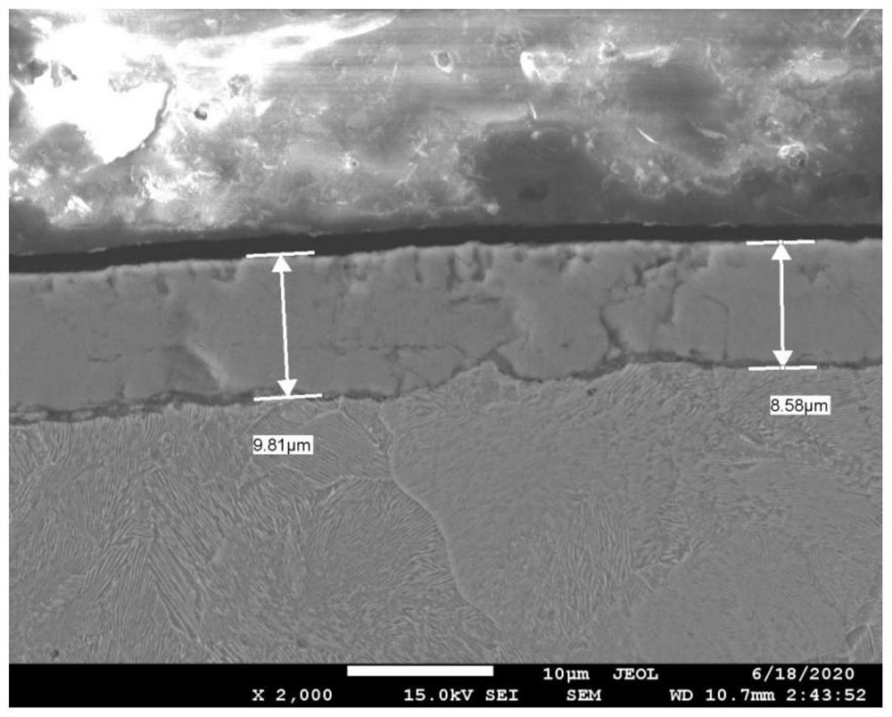
[0032] Production of cord steel with a specification of φ5.5mm, composition design C: 0.69%-0.76%; Mn: 0.46%-0.6%; Si: 0.15%-0.3%, Cr≤0.06%; After the billet is rolled at a high line speed, The silk is spun at a spinning temperature of 900°C, and coiled into coils on the air-cooled roller table. The coil is conveyed forward by the air-cooled roller table for controlled cooling. The fan is turned off in the early stage, and the coil passes through the roller table until the temperature reaches 800°C. Then turn on the fan to cool the coil quickly, and cool the coil quickly at a cooling rate of 33.25°C / s. After passing through the Ar3~Ar1 interval, control the cooling rate to slowly cool the phase transition zone. Before the temperature reaches the phase transition point, according to the production environment part Turn on the air cooling of the cooling roller line to let the coil cool down to the phase transition point at a cooling rate of 5°C / s. After reaching the phase transit...

Embodiment 2

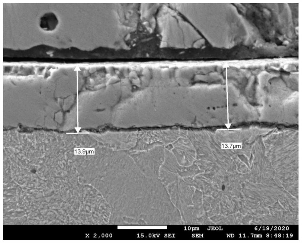
[0035]Production of cord steel with a specification of φ5.5, composition design C: 0.79%-0.86%; Mn: 0.46%-0.6%; Si: 0.15%-0.3%, Cr≤0.06%; After the billet is rolled at a high line speed, Spinning at a spinning temperature of 910°C, the wire rod is rolled into a coil on the roller table, and is continuously conveyed by the roller table into the air-cooled roller table for wire-controlled cooling. When entering the cooling control zone, the coil temperature is 880°C, and the coil is naturally cooled to 800°C to equalize the temperature of the coil after passing through the roller table. The coil enters the fast cooling stage. Turn on the air cooling and use the cooling rate of 28.5°C / s to quickly cool the coil. After cooling through the Ar3~Ar1 interval, control the cooling rate to perform slow cooling in the phase transition zone. When the wire temperature is close to the phase transition temperature, The wire is greatly affected by cooling. At this time, turn off the fan (or c...

Embodiment 3

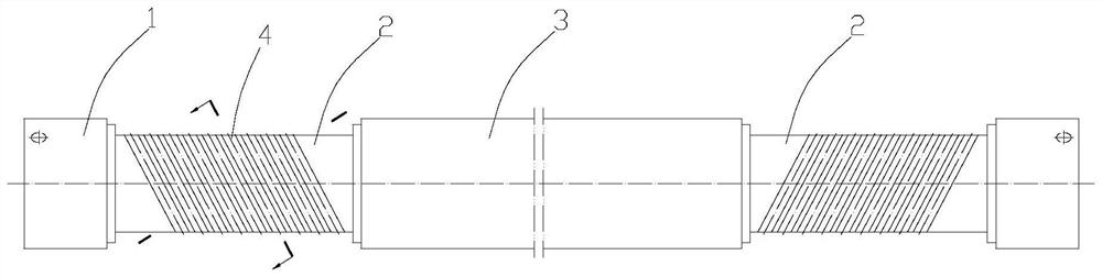
[0038] This embodiment involves the transformation of the idler rollers in the air-cooled roller table line. The reason for the transformation is that the cooling line idler rollers cool slowly on both sides and fast in the middle, that is, the cooling rate of the coils at the overlapping points on both sides is relatively slow. In order to solve this problem, this application has made related improvements to the structure of the idler roll: the idler roll is designed as a roll head 1 at both ends, a roll body 3 in the middle, and a roll neck 2 between the roll body 3 and the two roll heads 1 , the ring diameter of the roll body 3 is greater than the ring diameter of the roll neck 2, and the left and right overlapping points of the wire rod coil on the idler roller correspond to the upper and lower sides of the two roll necks 2 respectively, and the coils between the left and right overlapping points correspond to the roll body 3, so The air cooling of the cooling control rolle...


PUM

PropertyMeasurementUnit
Phase transition temperatureaaaaaaaaaa
Tensile strengthaaaaaaaaaa

Abstract

The invention relates to a production method for tire cord steel. The production method comprises the following steps that (1) the spinning temperature is controlled to be 885-945 DEG C; and (2) a steel wire rod subjected to spinning is collected and coiled into a continuous coil on a roller way, and controlled cooling is carried out on the coil on the roller way, which relates to a natural temperature equalization stage; a rapid cooling stage, wherein the coil rapidly passes through an Ar3-Ar1 temperature interval so as to increase the content of FeO in an oxide layer on the surface of the coil; a slow cooling stage, wherein before a sorbite phase transformation point, the coil is slowly cooled towards the phase transformation point, after the phase transformation point is reached, due to the fact that a structure can release phase transformation latent heat, the temperature of the wire is rapidly increased again, at the moment, air cooling needs to be gradually started or turned up, and the temperature increasing speed of the coil is controlled within 10 DEG C/s till phase transformation is completed; and a natural slow cooling stage, wherein the coil subjected to phase transformation continues to be naturally and slowly cooled to the room temperature on a controlled cooling roller line. According to the method, the oxide on the surface layer of the steel wire rod meets the requirement of mechanical stripping, in addition, net carbon can be well controlled, and in addition, the stability and uniformity of the mechanical property of a cleaning rod are obviously improved.

Description

technical field [0001] The invention relates to the technical field of wire rod steel, in particular to a production method of cord steel. Background technique [0002] Cord steel wire rod is an important raw material for the production of car tires, engineering machinery tires, truck tires, aircraft tires and other skeleton materials for rubber products. In production, the user needs to draw the wire rod to 0.15-0.38mm and twist it into strands. Therefore, the requirements for the surface quality, structure and performance of the cord steel wire rod are relatively high. When the mechanical properties or metallographic structure of cord steel wire rods are not up to standard, it is easy to cause fatigue fracture during subsequent drawing and twisting, which seriously affects the production rhythm. At the same time, due to the ever-increasing environmental protection production requirements, customers are forced to use mechanical stripping instead of pickling to remove the o...

Claims


Application Information

Patent Timeline
IPC IPC(8): B21B1/16B21B37/74B21B45/02
CPCB21B1/16B21B37/74B21B45/0203
Inventor 孙逸澄刘海何佳锋陈海燕黄伟蒋莹唐小俭沈星澄
Owner JIANGYIN XINGCHENG GOLD MATERIALS CO LTD
Why Eureka
Try Eureka