Radiator with double phase change cavities

A radiator and dual-phase change technology, applied in indirect heat exchangers, cooling/heating devices of lighting devices, lighting and heating equipment, etc. Dry out and other problems, to achieve the power density heat dissipation requirements, improve heat extraction capacity, and improve performance

Pending Publication Date: 2022-01-11
INST OF ENGINEERING THERMOPHYSICS - CHINESE ACAD OF SCI +1
View PDF0 Cites 0 Cited by
  • Summary
  • Abstract
  • Description
  • Claims
  • Application Information

AI Technical Summary

Problems solved by technology

However, due to the problem of the maximum liquid filling rate of the traditional phase change radiator, when working at a large angle, the phase change working medium cannot be returned to the evaporation surface in time, and even the liquid phase change working medium is completely separated from the evaporation surface, resulting in the complete evaporation of the evaporation surface. In the case of dryness, it will eventually lead to the failure of the radiator and seriously affect the reliability of the equipment or even burn the equipment

Method used


Image

  • Radiator with double phase change cavities
  • Radiator with double phase change cavities
  • Radiator with double phase change cavities

Examples


Embodiment 1

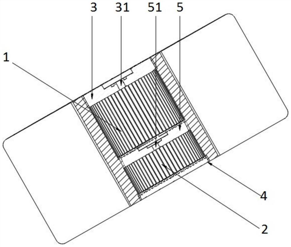
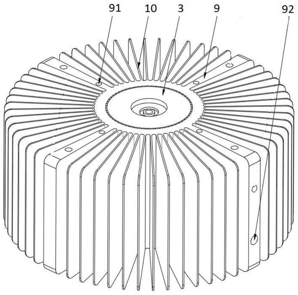
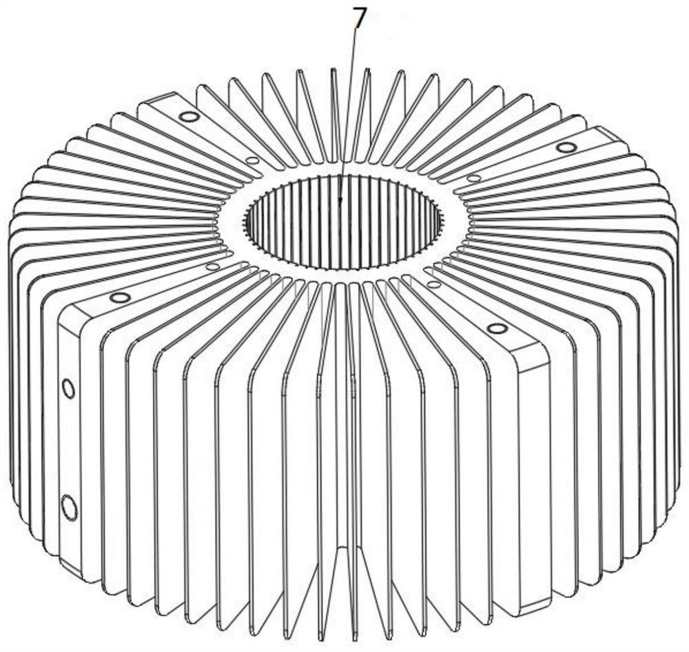
[0035] Such as Figure 1~3 As shown, a radiator with a dual-phase change cavity, the main structure is sunflower-shaped, the material is at least one of metal, alloy, plastic or metal-plastic, the outer diameter is 20~500mm, the inner diameter is 10~400mm, the total height 20~500mm. It includes an upper cavity body 1 , a lower cavity body 2 , an upper cover plate 3 , a lower cover plate 4 and a sandwich plate 5 .

[0036] The upper cover plate 3 has an outer diameter of 10-400 mm and a thickness of 5-15 mm. It cooperates with the upper cavity 1 and is arranged on the top of the upper cavity 1. The upper surface center of the upper cover plate 3 is provided with a first sealing port 31, such as Figure 6 shown. The lower cover plate 4 has an outer diameter of 10-400 mm and a thickness of 5-15 mm, which cooperates with the lower cavity 2 and is arranged at the bottom of the lower cavity 2 .

[0037] The sandwich plate 5 has an outer diameter of 10-400 mm and a thickness of 5-...


PUM


Abstract

The invention discloses a radiator with double phase change cavities, and belongs to the technical field of heat dissipation and cooling. An upper cavity and a lower cavity of the radiator are vacuum cavities, an upper cover plate is arranged at the top end of the upper cavity, a first packaging opening is formed in the center of the upper surface of the upper cover plate, a lower cover plate is arranged at the bottom end of the lower cavity, and a sandwich plate is arranged between the upper cavity and the lower cavity; the upper surface of the sandwich plate is an evaporation surface of the upper cavity, a second packaging opening is formed in the center of the upper surface of the sandwich plate, and the lower surface of the sandwich plate is a condensation surface of the lower cavity; an evaporation surface, which is in contact with the lower cavity, of the lower cover plate is a reinforced surface, and an evaporation surface, which is in contact with the upper cavity, of the sandwich plate is a reinforced surface; phase change working media are arranged inside the upper cavity and the lower cavity, and the boiling point of the phase change working medium in the lower cavity is higher than that of the phase change working medium in the upper cavity when the vacuum degree of the upper cavity is identical to that of the lower cavity; the vacuum degree of the upper cavity is higher than that of the lower cavity when the boiling point of the phase change working medium in the upper cavity is identical to that of the phase change working medium in the lower cavity. The radiator has the advantages that the radiator is high in heat exchange capacity, the condensation backflow distance can be shortened, the liquid supplementing rate and capacity can be improved, the problem of local hot spots of existing evaporation surfaces can be solved, and application requirements on large inclination angles and high power density can be met.

Description

technical field [0001] The invention belongs to the technical field of heat dissipation and cooling, and in particular relates to a radiator with a dual-phase change cavity. Background technique [0002] At present, power electronic devices such as electronics and optoelectronic chips are gradually tending to high power, miniaturization, high integration, and high frequency, followed by new standards and high requirements for heat dissipation technology. Taking high-power LEDs as an example, nearly 80% to 90% of the input power is converted into heat energy. If the heat cannot be discharged in time, it will seriously affect the light effect and service life of LED lamps. However, the compact structure of power electronic devices only allows a limited heat dissipation space, and requires low noise and low power consumption for heat dissipation, so the traditional air cooling can no longer meet the cooling requirements. The heat dissipation system has become the subject of ex...

Claims


Application Information

Patent Timeline
Patent Type & Authority Applications(China)
IPC IPC(8): F21V29/51F21V29/503F21V29/77H05K7/20F28D15/02F28D15/04
CPCF21V29/51F21V29/503F21V29/77H05K7/20H05K7/20309F28D15/02F28D15/046H05K7/20336
Inventor 董宜放于樱迎胡学功
Owner INST OF ENGINEERING THERMOPHYSICS - CHINESE ACAD OF SCI
Why Eureka
Try Eureka