
Tower type camera structure applied to coaxial four-mirror optical system

An optical system and tower-type technology, which is applied in the field of tower-type camera structures, can solve the problems of not meeting the high rigidity requirements of large-scale space cameras, reducing the thermal stability of camera structures, and the influence of camera optical systems, etc., achieving good athermalization effects and good The effect of structural stability and compact structure

Active Publication Date: 2022-01-25
CHANGCHUN INST OF OPTICS FINE MECHANICS & PHYSICS CHINESE ACAD OF SCI
View PDF4 Cites 0 Cited by
  • Summary
  • Abstract
  • Description
  • Claims
  • Application Information

AI Technical Summary

Problems solved by technology

[0009] The space camera structure can be divided into three main structural forms according to the mirror support method. The first is the thin-wall connection cylinder type. Rigidity requirements, and generally the connecting cylinder also acts as an external light-shielding cylinder, which will reduce the thermal stability of the camera structure; the second type uses a truss-type camera structure, which has the characteristics of high specific stiffness and light weight, but This truss structure is generally arranged outside the camera. When the camera receives an external mechanical impact, the truss structure will directly affect the support of the mirror, thereby affecting the optical system of the camera.

Method used


Image

  • Tower type camera structure applied to coaxial four-mirror optical system
  • Tower type camera structure applied to coaxial four-mirror optical system
  • Tower type camera structure applied to coaxial four-mirror optical system

Examples


Embodiment Construction

[0122] In order to enable those skilled in the art to better understand the technical solutions of the present invention, the present invention will be further described in detail below in conjunction with the accompanying drawings.

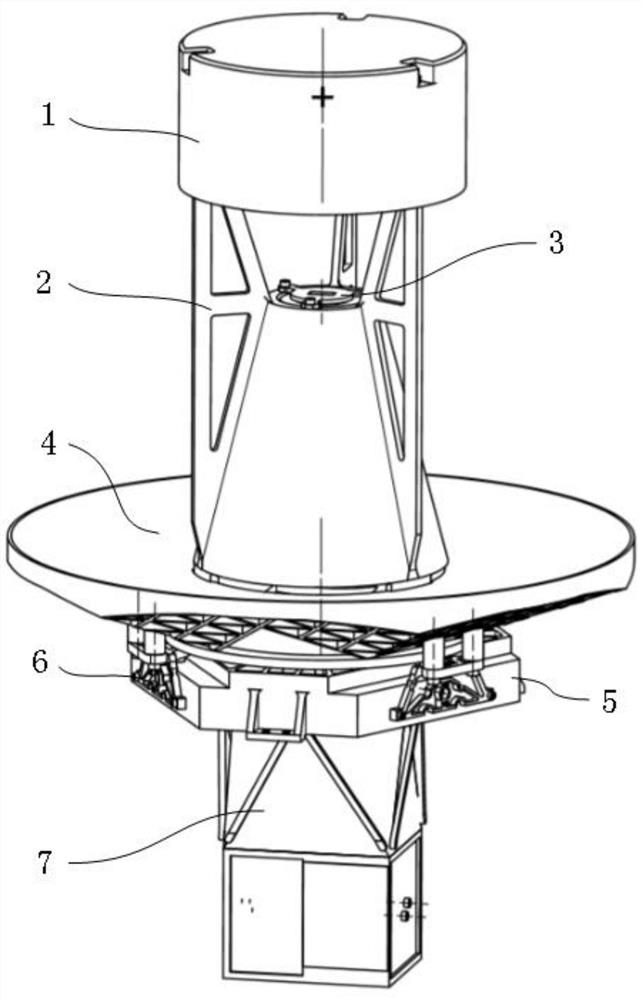
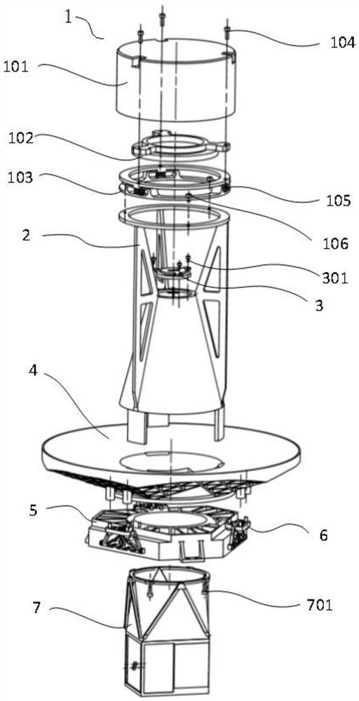
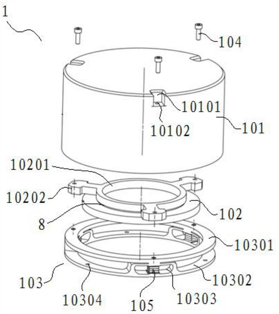
[0123] see Figure 1 to Figure 11 shown;

[0124] A tower camera structure applied to a coaxial four-mirror optical system of the present invention, the tower camera structure includes:

[0125] Main three mirrors 4;

[0126] The secondary mirror assembly 1 integrated on the side of the reflecting surface of the primary three mirror 4 through the supporting tower 2;

[0127] The secondary mirror assembly 1 is coaxial with the primary three mirrors 4, and the four mirrors 3 arranged coaxially with the secondary mirror assembly 1 and the primary three mirrors 4 are installed on the supporting tower 2;

[0128] The tower camera structure also includes:

[0129] Substrate 5;

[0130] The substrate 5 is assembled on the back of the main three mirro...


PUM


Abstract

The invention discloses a tower-type camera structure applied to a coaxial four-mirror optical system. The tower-type camera structure comprises a main three-mirror and a secondary mirror assembly integrated on the main three-mirror through a bearing tower; the bearing tower is provided with a fourth mirror which is coaxially arranged with the secondary mirror assembly and the main third mirror; and the tower-type camera structure also comprises a substrate which is assembled on the back surface of the main third mirror through a flexible supporting member. A focal plane assembly is assembled on the side, away from the main third mirror, of the substrate. The bearing tower, the main third mirror, the substrate and the flexible support member form a lightweight structure. According to the tower type camera structure, the thermal stability and the structural stability are improved, the secondary mirror, the secondary mirror cover, the flexible structure, the force bearing tower, the main third mirror, the main fourth mirror and the substrate are all made of beryllium aluminum alloy, and the reflecting mirror and the supporting structure are made of the same material, so that an optical system can achieve the optimal athermalization effect and good force and heat bearing performance. Meanwhile, the beryllium aluminum alloy has the characteristics of low density, high rigidity and high specific rigidity, so that the space camera has good structural stability.

Description

technical field [0001] The invention relates to the technical field of space camera structures, in particular to a tower camera structure applied to a coaxial four-mirror optical system. Background technique [0002] At present, the space remote sensing optical system is developing in the direction of long focal length, large width, small size and light weight. Due to the advantages of no chromatic aberration, small size and light weight, the reflective optical system has been widely used in the space remote sensing system. [0003] Reflective systems are mainly divided into coaxial systems and off-axis systems. [0004] The off-axis reflector system has no obstruction, large field of view, and high imaging quality. However, compared with the shortcomings of the coaxial reflector system, which are large in size and difficult to install and adjust, it is not suitable for smaller satellite platforms and the integrated design of payload and platform. In order to reduce the vol...

Claims


Application Information

Patent Timeline
Patent Type & Authority Applications(China)
IPC IPC(8): G03B17/17G02B17/06G02B7/182
CPCG03B17/17G02B17/06G02B7/182
Inventor 徐伟李云峰李宗轩张德福王天聪
Owner CHANGCHUN INST OF OPTICS FINE MECHANICS & PHYSICS CHINESE ACAD OF SCI
Learn More