Gear ring forming process
A molding process and ring gear technology, which is applied to casting molding equipment, molds, cores, etc., can solve problems such as low production efficiency, poor impact toughness, and coarse metal grains of castings, so as to reduce labor intensity and realize The effect of mechanical automation and dense metallographic structure
- Summary
- Abstract
- Description
- Claims
- Application Information
AI Technical Summary
Problems solved by technology
Method used
Image
Examples
Embodiment 1
[0035] Ring gear molding process of the present invention comprises the following steps:
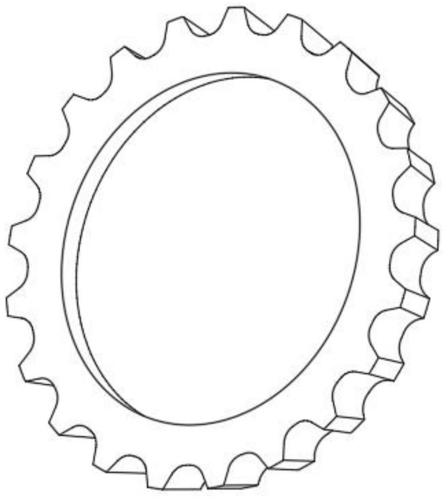
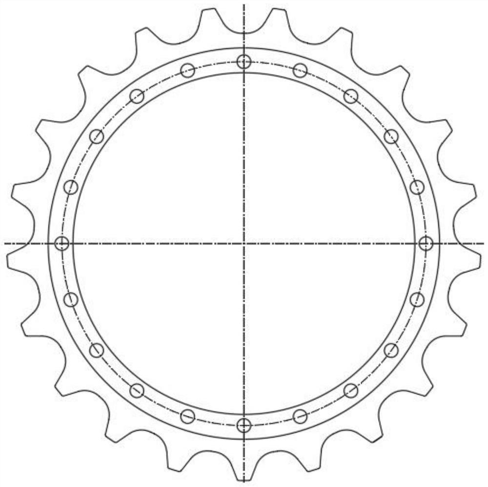
[0036] S1 billet forming: smelting the manganese steel alloy in the open hearth furnace to make the manganese steel alloy into a molten state, casting the molten manganese steel alloy into the ring gear mold to form the ring gear blank ring 14;
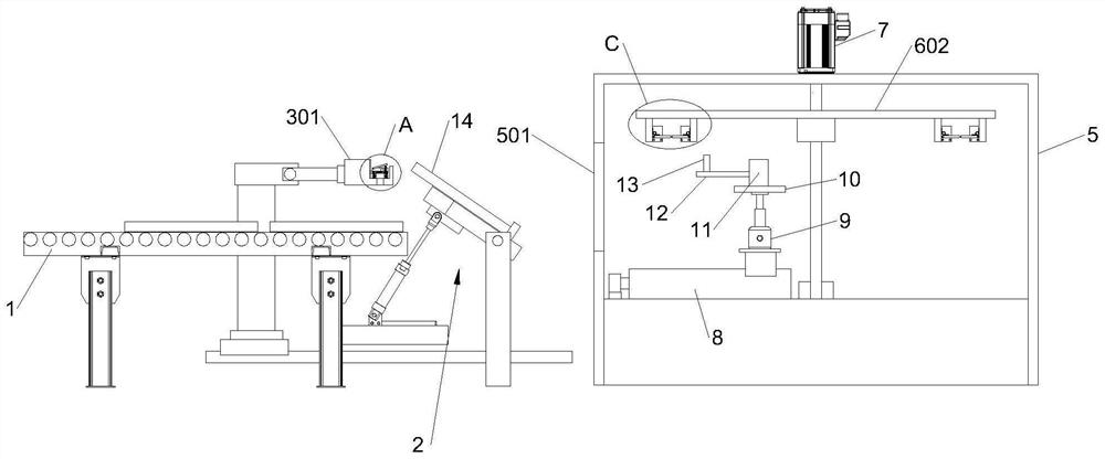
[0037] S2 quenching and tempering treatment: taking out the ring gear blank ring 14, and transporting the ring gear blank ring 14 to the incubator 5 through an automatic conveying device for quenching and tempering treatment;
[0038] S3 Forming: Take out the ring gear blank ring 14 after quenching and tempering treatment, and form the ring gear body by machining.
[0039] After adopting the above-mentioned technical scheme: the manufacturing process of the fire ring gear of the present invention no longer uses traditional ring gear manufacturing processes such as sea sand for casting, modeling sand, steam cutting, etc., which has a positive eff...
Embodiment 2
[0041] The automatic conveying device includes a conveying unit 1, the ring gear blank ring 14 is horizontally placed on the upper end of the conveying unit 1, and the conveying unit 1 is provided with an overturning assembly 2 at the rear along the conveying direction, and the overturning assembly 2 is used to make the ring gear blank ring 14 in an inclined state, The top of the conveying unit 1 is provided with a transfer assembly 3, the lower end of the transfer assembly 3 is provided with a horizontal drive assembly, the overturn assembly 2 is provided with an incubator 5 side by side, the incubator 5 is provided with a suspension assembly 6, and the transfer assembly 3 is used to turn the overturn assembly 2. The ring gear blank ring 14 at the upper end is transferred to the suspension assembly 6.
[0042]After adopting the above technical solution: the conveying unit 1 is a roller conveying line as one of the preferred structures, and the ring gear blank moves horizontall...
Embodiment 3
[0044] The turning assembly 2 includes a side guard 201, a turning plate 206, a pin 204 and a hydraulic rod 203; the side guard 201 is arranged behind the conveying unit 1 along the conveying direction, and the turning plate 206 is hinged to the side guard 201 through the pin 204. , the pin shaft 204 is located at the end of the turnover plate 206 away from the delivery unit 1, the upper end of the hydraulic rod 203 is hinged to the lower end of the end of the flip plate 206 away from the pin shaft 204, the lower end of the hydraulic rod 203 is provided with a support plate 202, and the hydraulic rod 203 is connected to the The support plate 202 is hingedly arranged.
[0045] A limiting plate 205 is disposed on the upper end of the turnover plate 206 , and the limiting plate 205 is located on a side away from the conveying unit 1 .
[0046] After adopting the above technical scheme:
[0047] The overturning plate 206 can rotate around the axis of the pin shaft 204 to change t...
PUM
 Abstract
Description
Claims
Application Information
 - R&D
- Intellectual Property
- Life Sciences
- Materials
- Tech Scout
- Unparalleled Data Quality
- Higher Quality Content
- 60% Fewer Hallucinations
Browse by: Latest US Patents, China's latest patents, Technical Efficacy Thesaurus, Application Domain, Technology Topic, Popular Technical Reports.
© 2025 PatSnap. All rights reserved.Legal|Privacy policy|Modern Slavery Act Transparency Statement|Sitemap|About US| Contact US: help@patsnap.com


