Loose metal sintering layer section observation method and ion grinding device

A metal sintering and cross-section technology, applied in metal processing equipment, grinding devices, grinding machine tools, etc., can solve the problems of inability to observe the degree of dispersion of the catalytic body from the cross-section, the separation of the surface catalytic body from the carrier plate, and the reduction of the convenience of the catalytic body. , to achieve the effect of improving convenience, improving grinding quality and efficiency, and reducing the probability of falling off

Pending Publication Date: 2022-01-28
深圳市美信咨询有限公司
View PDF0 Cites 0 Cited by
  • Summary
  • Abstract
  • Description
  • Claims
  • Application Information

AI Technical Summary

Problems solved by technology

[0005] In view of the above-mentioned related technologies, the inventor believes that there are the following defects: in the process of mechanical grinding, due to the large stress, the surface catalytic body is easily detached from the carrier plate, and when the catalytic body falls off, it is difficult or even impossible to observe the catalytic body from the cross section The degree of dispersion and the combination with the substrate reduce the convenience of observing the catalyst body

Method used


Image

  • Loose metal sintering layer section observation method and ion grinding device
  • Loose metal sintering layer section observation method and ion grinding device
  • Loose metal sintering layer section observation method and ion grinding device

Examples


Embodiment 1

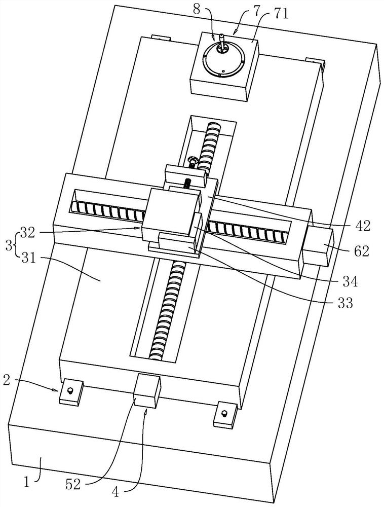
[0076] refer to figure 1 , the cross-section observation method of loose metal sintered layer, comprises the following steps:

[0077] S1. Clamp the sample to the fixture 3, and the upper surface of the sample protrudes from the fixture 3. The fixture 3 has a variety of fixtures 3 of different specifications and sizes, so as to adapt to the clamping of samples of different sizes, and then the fixture 3 and the sample is placed on the detection platform 1, and the sample is observed by the observer, and the specific position to be observed is selected from the sample after moving the sample. The observer can be a microscope or a scanning electron microscope;

[0078] S2. Place the jig 3 on the cutting machine according to the specific position obtained in S1, and the cutting machine 11 starts to cut the position of the sample on the jig 3 that needs to be observed into a specified small-sized sample. The specified required size is generally no more than 2cm× in length and width...

Embodiment 2

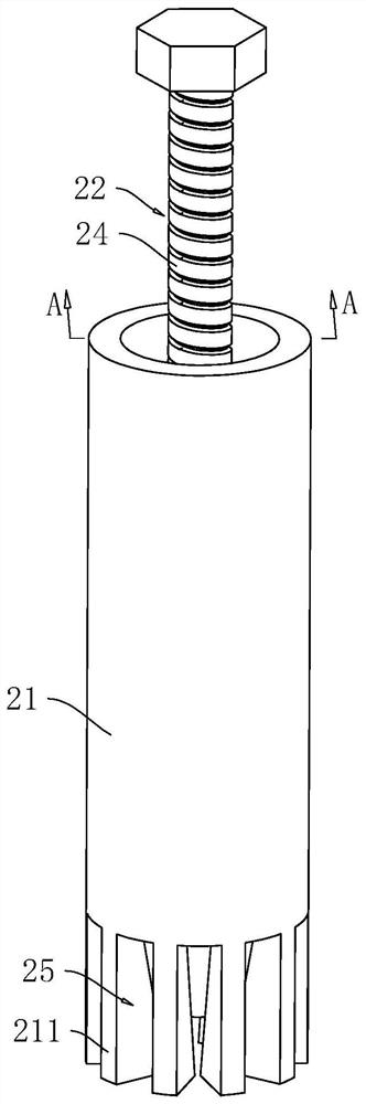
[0111] refer to Figure 8 , The difference between this embodiment and Embodiment 1 is that the fixing assembly 22 includes an electromagnet 28 and a control switch 29, and there are four electromagnets 28 fixedly installed on the lower surfaces of the four connecting seats 311, and the electromagnets 28 Located between the socket pipe 21 and the base 31, the lower surface of the electromagnet 28 is flush with the lower surface of the base 31, and the electromagnet 28 is adsorbed on the detection table 1 after being energized; the control switch 29 is fixedly installed on the side wall of the base 31, and The control switch 29 is electrically connected with the four electromagnets 28 , and the control switch 29 controls the power on and off of the four electromagnets 28 .

[0112] The working principle of the embodiment of the present application is:

[0113] The control switch 29 is activated so that the four electromagnets 28 are energized, and the four electromagnets 28 ar...


PUM


Abstract

The invention relates to a loose metal sintering layer section observation method and an ion grinding device, and relates to the technical field of metal sintering layers. The loose metal sintering layer section observation method comprises the following steps of S1, selecting an observation position through an observer; S2, cutting a sample into small-size samples by a cutting machine; S3, grinding the small-size samples by a grinding machine; S4,observing the position needing to be cut through the observation instrument; S5, cutting the sample by an ion grinder to obtain an observation section; S6, observing the cross section by using an observation instrument, wherein a clamp is detachably connected with a detection table, the cutting machine, the grinding machine and the ion grinding instrument. The observation position of the sample is observed and selected through the observation instrument, then the small-size samples are obtained through cutting via the cutting machine, then the small-size samples are subjected to coarse grinding, the observation instrumentcontinues to observe and select the position needing to be cut, then the ion grinding instrument starts accurate grinding to obtain the observation section, and finally the observation section is observed through the observation instrument, so that the convenience of section observation is improved.

Description

technical field [0001] The present application relates to the technical field of metal sintered layers, in particular to a cross-sectional observation method and ion milling equipment of a loose metal sintered layer. Background technique [0002] When the fuel cladding of the reactor core in a nuclear power plant fails in a large area, threatening or destroying the pressure vessel and containment of the nuclear power plant, it is called a severe nuclear power accident. A large amount of hydrogen generated during the process and hydrogen explosion are the main reasons for the failure of pressure vessels and containment vessels. [0003] In order to eliminate the hydrogen in the space, placing a passive hydrogen elimination recombiner is a hydrogen elimination measure that can be widely used in the nuclear power space, and the noble metal Pd will also be used in most hydrogen recombination catalysis. For heterogeneous catalysis, obtaining more contact area between the catalys...

Claims


Application Information

Patent Timeline
Patent Type & Authority Applications(China)
IPC IPC(8): G01N1/28G01B11/00B24B1/00B24B37/00B24B37/34B24B37/27
CPCG01N1/286G01B11/00B24B1/00B24B37/00B24B37/34B24B37/27G01N2001/2866G01N2001/2873
Inventor 曾志卫
Owner 深圳市美信咨询有限公司
Why Eureka
Try Eureka