Ultra-stable laser device laser self-adaptive coupling cavity-entering matching system and method

A laser, self-adaptive technology, applied in the field of laser, can solve the problem of difficult matching between laser and F-P cavity, and achieve the effect of simple structure, automatic adjustment and correction, and high matching accuracy of cavity

Active Publication Date: 2022-01-28
HANGZHOU INST FOR ADVANCED STUDY UCAS
View PDF7 Cites 1 Cited by
  • Summary
  • Abstract
  • Description
  • Claims
  • Application Information

AI Technical Summary

Problems solved by technology

[0005] The first purpose of the present invention is to provide an ultra-stable laser laser adaptive coupling into cavity matching system for

Method used


Image

  • Ultra-stable laser device laser self-adaptive coupling cavity-entering matching system and method
  • Ultra-stable laser device laser self-adaptive coupling cavity-entering matching system and method
  • Ultra-stable laser device laser self-adaptive coupling cavity-entering matching system and method

Examples


Embodiment 1

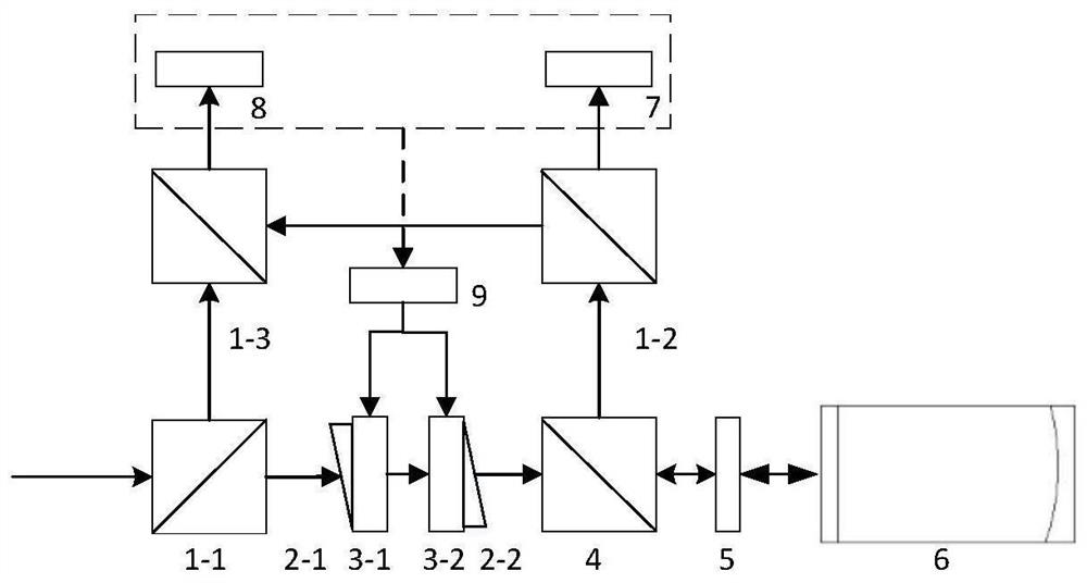
[0058] combine Figure 1-Figure 3 As shown, an ultra-stable laser of the present invention is adaptively coupled into the cavity matching system. A 10mW laser beam first passes through the first beam splitting prism 1-1, wherein 3mW of light is reflected, and then passes through the third beam splitting prism 1-1. 3 After transmission, 1.5 mW of reference light enters the four-quadrant photodetector 8.

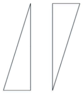
[0059] The 7mW light transmitted by the first beam splitter prism passes through the first wedge prism 2-1, the second wedge prism 2-2, the polarization beam splitter prism 4, and the 1 / 4 wave plate 5, enters the F-P cavity 6, and is reflected back by the F-P cavity 6 After passing through the 1 / 4 wave plate 5 again, the light enters the polarizing beam splitting prism 4. After being reflected by the polarizing beam splitting prism 4, it enters the second beam splitting prism 1-2 for beam splitting. At the second beam splitting prism 1-2, the signal of 3mW The light transmits...

Embodiment 2

[0063] like Figure 4 As shown in the present invention, an ultra-stable laser laser adaptively coupled into the cavity matching system, a beam of 10mW laser first passes through the first beam splitting prism 1-1, wherein the 3mW light is reflected and passes through the 1 / 2 wave plate 10 After the polarization direction is adjusted, the reference light of 1.5 mW enters the four-quadrant photodetector 8 after being transmitted through the third beam splitting prism 1-3. The 7mW light transmitted by the first beam splitter prism passes through the first wedge prism 2-1, the second wedge prism 2-2, the polarization beam splitter prism 4, and the 1 / 4 wave plate 5, enters the F-P cavity 6, and is reflected back by the F-P cavity 6 After passing through the 1 / 4 wave plate 5 again, the light enters the polarizing beam splitting prism 4. After being reflected by the polarizing beam splitting prism 4, it enters the second beam splitting prism 1-2 for beam splitting. At the second bea...


PUM


Abstract

The invention provides an ultra-stable laser device laser self-adaptive coupling cavity-entering matching system and method, and the method comprises the steps: the precise measurement of light beam pointing is achieved through a charge coupling element light spot mass center detection technology and a four-quadrant photoelectric detector phase detection technology, and the offset of an F-P cavity is obtained; besides, a wedge-shaped prism pair is adjusted through a stepping motor to achieve precise adjustment of a laser light path, precise measurement of light beam pointing and precise adjustment of the light path form a closed loop, and active compensation of F-P cavity position deviation is achieved. According to the laser self-adaptive coupling in-cavity matching system and method for the ultra-stable laser, the structure is simple, adjustment and correction are automatic, the in-cavity matching precision is high, and the system and method have wide application prospects in the fields of ultra-stable lasers in space application and optical communication.

Description

technical field [0001] The invention relates to the field of laser technology, in particular to an ultra-stable laser laser self-adaptive coupling-in-cavity matching system and method. Background technique [0002] Space high-precision time-frequency systems have important application requirements in the next-generation deep space exploration, navigation, geodesy, military, and basic scientific research. China, the United States and the European Union attach great importance to it. As the local oscillation source of SOC, ultra-stable laser (USL) determines the short-term and medium-term stability of SOC, and directly affects the overall performance of spatial high-precision time-frequency system. Therefore, it is of great significance and value to study the USL suitable for space applications. [0003] The space application of USL still faces many scientific and technical problems, and the difficulty of maintaining high-precision mode matching between the laser and the F-P...

Claims


Application Information

Patent Timeline
IPC IPC(8): H01S3/13G06T7/80
CPCH01S3/1305G06T7/80
Inventor 孟令强孟范超赵芃杨崔钊杨翠婷熊君炀牛泽瑞李泽坤邢成文王青俣邓久昌边伟贾建军亓洪兴王建宇
Owner HANGZHOU INST FOR ADVANCED STUDY UCAS
Why Eureka
Try Eureka