Differential electrochemical mass spectrometry flow electrolytic cell for carbon neutralization test, and design method thereof

A flow electrolytic cell and electrochemical technology, applied in the field of electrochemistry, can solve the problems of low detection value, distorted product information, aggravated mass transfer limitation of reactants, etc., to improve time resolution, alleviate mass transfer limitation, and improve selectivity. Effect

Active Publication Date: 2022-02-01
SHANGHAI JIAO TONG UNIV
View PDF6 Cites 3 Cited by
  • Summary
  • Abstract
  • Description
  • Claims
  • Application Information

AI Technical Summary

Problems solved by technology

[0002] Traditional analytical techniques such as gas chromatography (GC) and nuclear magnetic resonance (NMR) are far from adequate for surface-regulated reactions such as carbon dioxide reduction (CO2) due to their inherent hysteresis. 2 RR) detection needs
Currently, for CO 2 RR product detection mostly uses off-line detection technology, which cannot reflect the information on the electrode surface during the electrochemical reaction in real time, which will lead to product information distortion. For active intermediates such as acetaldehyde, first collection and then detection will inevitably lead to detection values ​​lower than the actual output.
[0003] Secondly, for the thin-layer flow batteries currently in use, the micromilliliter-level flow rate is used in conjunction with the small chamber volume, which improves the collection efficiency but aggravates the mass transfer limitation of the reactants.

Method used


Image

  • Differential electrochemical mass spectrometry flow electrolytic cell for carbon neutralization test, and design method thereof
  • Differential electrochemical mass spectrometry flow electrolytic cell for carbon neutralization test, and design method thereof
  • Differential electrochemical mass spectrometry flow electrolytic cell for carbon neutralization test, and design method thereof

Examples


Embodiment Construction

[0025] Reference will now be made in detail to the exemplary embodiments, examples of which are illustrated in the accompanying drawings. When the following description refers to the accompanying drawings, the same numerals in different drawings refer to the same or similar elements unless otherwise indicated. The implementations described in the following exemplary examples do not represent all implementations consistent with the present disclosure. Rather, they are merely examples of apparatuses and methods consistent with aspects of the presently disclosed embodiments as recited in the appended claims.

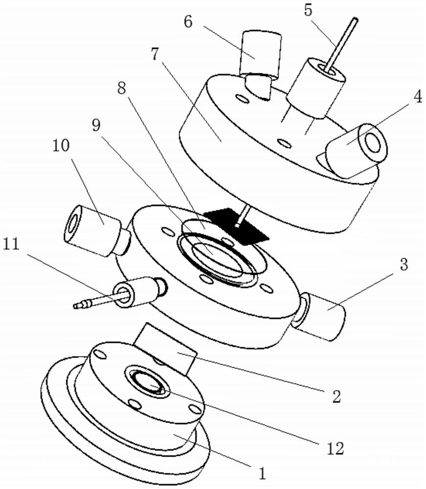
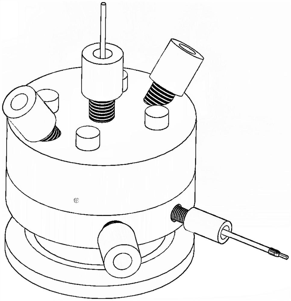
[0026] see Figure 1-Figure 2 , in one embodiment provided by the present invention, a kind of differential electrochemical mass spectrometry flow electrolytic cell for carbon neutrality test comprises half-cell body, electrode system and mass spectrometer vacuum system, is provided with between two described half-cell bodies The ion exchange membrane 8 constitutes a mutu...


PUM

PropertyMeasurementUnit
volumeaaaaaaaaaa
volumeaaaaaaaaaa

Abstract

The invention relates to the technical field of electrochemistry, in particular to a differential electrochemical mass spectrum flow electrolytic cell for a carbon neutralization test, and a design method thereof. The differential electrochemical mass spectrum flow electrolytic cell comprises a half-cell body, an electrode system and a mass spectrum vacuum system, an ion exchange membrane is arranged between the two half cell bodies to form a cathode chamber and an anode chamber which are isolated from each other, and a sealing element is arranged to seal the cathode chamber and the anode chamber; the cathode chamber and the anode chamber respectively pass through capillary interfaces arranged on the corresponding half cell bodies, and two independent peristaltic pumps are used for driving and circulating electrolyte at a certain flow speed; and the lower part of the cathode chamber is connected with a mass spectrum sample inlet, and negative pressure sample introduction is carried out through a mass spectrum vacuum system. Reactants of electrochemical reaction are collected and detected in situ in real time, the time resolution of electrochemical characterization is improved, and higher experiment efficiency can be brought; and by arranging a working electrode and adopting a conductive composite film, information of substances near the electrode can be conveniently obtained.

Description

technical field [0001] The invention relates to the technical field of electrochemistry, in particular to a differential electrochemical mass spectrometry flow electrolytic cell for carbon neutralization testing and a design method thereof. Background technique [0002] Traditional analytical techniques such as gas chromatography (GC) and nuclear magnetic resonance (NMR) are far from adequate for surface-regulated reactions such as carbon dioxide reduction (CO2) due to their inherent hysteresis. 2 RR) detection needs. Currently, for CO 2 RR product detection mostly uses off-line detection technology, which cannot reflect the information on the electrode surface during the electrochemical reaction in real time, which will lead to product information distortion. For active intermediates such as acetaldehyde, first collection and then detection will inevitably lead to detection values ​​lower than the actual output. . [0003] Secondly, for the thin-layer flow batteries curr...

Claims


Application Information

Patent Timeline
Patent Type & Authority Applications(China)
IPC IPC(8): G01N27/28
CPCG01N27/28Y02E60/50
Inventor 蒋昆叶可
Owner SHANGHAI JIAO TONG UNIV
Why Eureka
Try Eureka