
Surface planarization method of semiconductor device

A surface planarization and semiconductor technology, applied in the field of surface planarization of semiconductor devices, can solve the problems of unsolved terminal area planarization, polysilicon residue treatment without terminal area, etc. Achieve precise control of the effect

Pending Publication Date: 2022-02-01
ZHUZHOU CRRC TIMES SEMICON CO LTD
View PDF4 Cites 0 Cited by
  • Summary
  • Abstract
  • Description
  • Claims
  • Application Information

AI Technical Summary

Problems solved by technology

[0008] However, the above method does not treat the polysilicon residue in the terminal area, and does not solve the planarization problem of the terminal area.

Method used


Image

  • Surface planarization method of semiconductor device
  • Surface planarization method of semiconductor device
  • Surface planarization method of semiconductor device

Examples


Embodiment 1

[0039] A method for planarizing a surface of a semiconductor device, comprising the steps of,

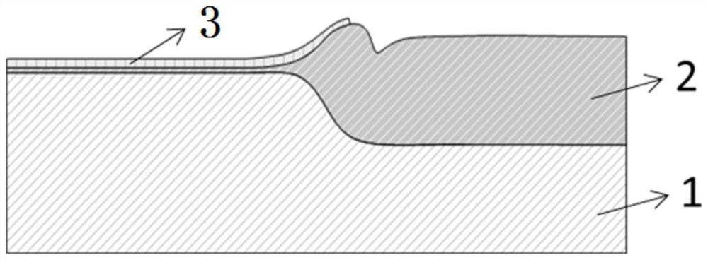
[0040] Step 1: If Figure 4 As shown, a cell region oxide layer 2 and silicon nitride 3 are deposited on a silicon substrate 1;

[0041] Step 2: If Figure 5 As shown, the open area formed by etching is oxidized to form an oxide layer 4 in the terminal area;

[0042] Step 3: If Figure 6 As shown, a hard mask layer 5 is deposited;

[0043] Step 4: If Figure 7 As shown, photolithography is performed first, and then the hard mask layer 5, the silicon nitride 3 and the oxide layer 2 of the cell region are etched;

[0044] Step 5: If Figure 8 As shown, a hard mask layer is used as an etching barrier layer to form trenches 6 in the active region;

[0045] Step 6: If Figure 9 As shown, the damaged layer in the trench is removed by dry etching, and then gate oxide oxidation is performed after the damaged layer is removed to obtain the gate oxide layer 7 after the damaged layer i...


PUM


Abstract

The invention relates to a surface planarization method of a semiconductor device, which comprises the steps of depositing an oxide layer and silicon nitride on a silicon substrate; oxidizing the open region to form a terminal region oxide layer; depositing a hard mask layer; carrying out photoetching, and then etching the hard mask layer; carrying out active region groove etching by taking the hard mask layer as an etching barrier layer; removing the damaged layer in the groove, and then growing a gate oxide layer; depositing polycrystalline silicon on the surface, and filling all the grooves with the polycrystalline silicon; carrying out CMP to flatten the surface of the wafer; synchronously etching the silicon nitride and the oxide layer, and staying on the oxide layer of a cellular region; and etching the polycrystalline silicon and the oxide layer which are higher than the silicon plane in the groove in the cellular region, and staying on the surface of the silicon substrate to realize planarization. According to the invention, polycrystalline silicon residues in a terminal area are avoided, an extra process does not need to be introduced to remove the hard mask layer, the process is simple, terminal point signal capturing can be accurately achieved, the planarization effect is achieved, and the uniformity of products is guaranteed.

Description

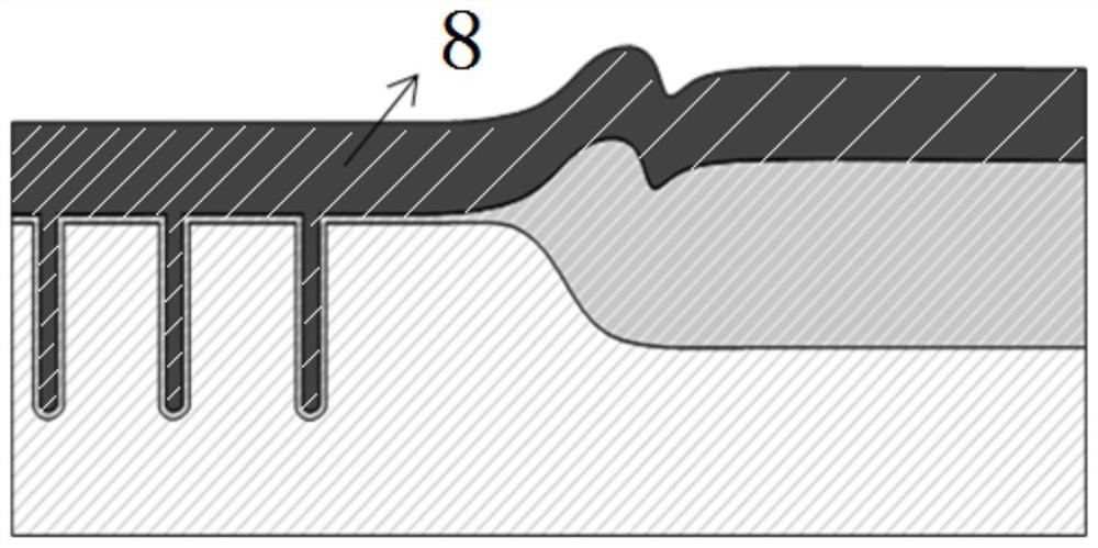
technical field [0001] The invention belongs to the technical field of semiconductor manufacturing, and in particular relates to a method for flattening the surface of a semiconductor device. Background technique [0002] At present, in the process of submicron-scale fine trench power devices, there will be a step such as figure 1 , followed by polysilicon deposition as figure 2 shown; as image 3 As shown, the CMP grinding process is performed on the polysilicon first, and then the CMP grinding process of the oxide layer in the terminal area is performed, and finally the global planarization of the wafer is achieved to prepare for the subsequent small line width process. This solution forms a bird's beak due to the oxidation of the terminal, and the polysilicon After deposition, it is very easy to cause polysilicon residue after grinding at the bird's beak, and staying on the oxide layer poses a greater challenge to the process. [0003] The technical solutions that are...

Claims


Application Information

Patent Timeline
Patent Type & Authority Applications(China)
IPC IPC(8): H01L21/3105H01L21/28
CPCH01L21/31051H01L29/401
Inventor 卜毅罗湘曾琪曾凯何逸涛冯宇
Owner ZHUZHOU CRRC TIMES SEMICON CO LTD
Learn More