Spray gun for plasma physical vapor deposition and preparation method of thermal barrier coating

A physical vapor deposition and plasma technology, applied in coating, ion implantation plating, metal material coating process, etc., can solve problems such as anode burn-through, unstable arc ignition, and inability to gasify powder, so as to increase the negative and positive The effect of inter-electrode distance, reduction of production cost, and reduction of current density

Active Publication Date: 2022-04-08
BEIHANG UNIV
View PDF6 Cites 0 Cited by
  • Summary
  • Abstract
  • Description
  • Claims
  • Application Information

AI Technical Summary

Problems solved by technology

For example, the current research has found that plasma physical vapor deposition cannot completely gasify the powder in most cases, and various particles (such as gas phase particles, liquid phase particles, partially melted particles, unmelted particles) are distributed in the wide plasma jet. etc.), is actually a coating preparation technology based on vapor deposition and multi-phase mixed deposition. The state and distribution of these particles in the jet flow cause differences in the coating structure and thickness of the workpiece surface, and also affect the coating. layer performance impact
[0005] There are generally two ways to improve the powder gasification rate in the process of plasma physical vapor deposition coating preparation. One is to further increase the power of the plasma arc generator. The power of the spray gun used for plasma vapor deposition is as high as 100 kW or more. High current (1500~3000A) and low voltage (usually below 38V) are used to achieve this. However, high power requires too much current density in the cathode, which will cause premature ablation of the cathode surface and the inner surface of the anode, resulting in unstable arc ignition. Moreover, the service life of the cathode and anode is low, and there may even be accidents caused by anode burn-through.
Another way to improve the powder gasification rate in the process of plasma physical vapor deposition coating preparation is to improve the sprayed ceramic powder so that it has both good fluidity and small particle size. The smaller the particle size of the powder, the better the powder The more fully the heating in the jet flow, the better the degree of gasification. However, fluidity and fine particle size are a pair of contradictions, and it is difficult to realize it at the same time. The fine powder must be granulated to meet the fluidity, and the agglomerated granulated powder needs to achieve gasification. Chemicalization must require the powder to have a specific secondary structure, which causes the price of raw materials to remain high and the cost of spraying to be too high
And the current spray guns for vapor deposition generally adopt radial powder feeding, and the powder cannot be sent to the center of the jet flow, resulting in low powder melting and gasification efficiency and low effective deposition area

Method used


Image

  • Spray gun for plasma physical vapor deposition and preparation method of thermal barrier coating
  • Spray gun for plasma physical vapor deposition and preparation method of thermal barrier coating
  • Spray gun for plasma physical vapor deposition and preparation method of thermal barrier coating

Examples


Embodiment 1

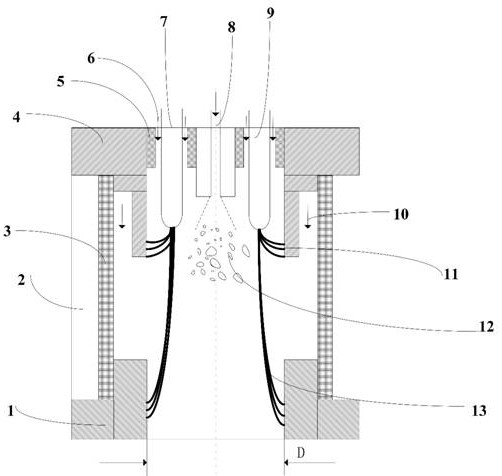
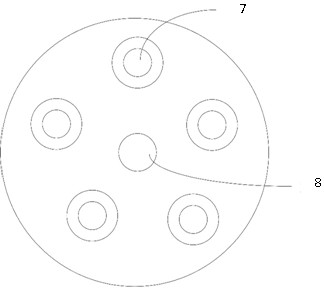
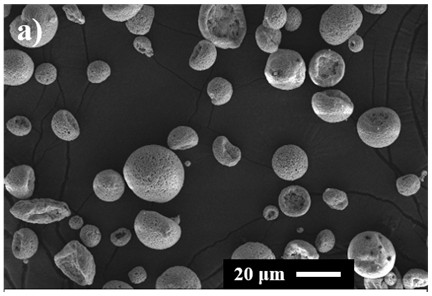
[0068] Using a five-cathode high-efficiency and low-cost plasma torch, the top view is as follows figure 2 As shown in the figure, the symmetrically distributed hollow water-cooled cathode and the powder feeding tube located on the central axis are selected as the working gas for arc ignition, and Ar and H are selected as the working gas when the arc is stable. 2 gas mixture. The spray gun was installed on the plasma physical vapor deposition equipment, and the YSZ powder was agglomerated and granulated. The powder D50 was 10-20 μm, and the powder morphology was spherical, such as Figure 3a shown,

[0069] The specific spraying steps are as follows:

[0070] Step 1: Close the vacuum chamber and evacuate so that the pressure of the vacuum chamber is lower than 0.08 mbar;

[0071] Step 2: Fill with Ar gas until the vacuum chamber pressure reaches 130 mbar;

[0072] Step 3: start the arc, start the arc between the hollow water-cooled cathode and the auxiliary anode at a low...

Embodiment 2

[0081] A three-cathode spray gun of the present invention is installed on the plasma physical vapor deposition equipment, and the columnar structure coating is prepared by using the ungranulated nano-powder, the nano-powder D50 is 0.5-1 μm, and the powder is irregular in shape, such as: Figure 4a shown. The specific spraying steps are as follows:

[0082] Step 1: Close the vacuum chamber and evacuate, so that the pressure of the vacuum chamber is lower than 0.08mbar;

[0083] Step 2: Fill with Ar gas until the vacuum chamber pressure reaches 130mbar;

[0084] Step 3: striking the arc, starting the arc between the hollow water-cooled cathode and the auxiliary anode at a low current of 30A and an Ar gas flow of 15L / min;

[0085] Step 4: Lengthen the plasma arc, after the plasma arc is stable, increase the current between the hollow water-cooled cathode and the water-cooled anode to 65A, adjust the Ar flow to 30L / min, H 2 The air flow is 30L / min, and the plasma arc is transfe...


PUM

PropertyMeasurementUnit
diameteraaaaaaaaaa
lengthaaaaaaaaaa

Abstract

The invention discloses a spray gun for plasma physical vapor deposition and a method for preparing a thermal barrier coating. Aiming at the problems of short lifespan of the cathode and anode of the plasma spray gun used in the existing plasma physical vapor deposition technology and high powder cost, the ceramic bushing and auxiliary anode are added. The design increases the distance between cathode and anode, axial powder feeding, 3‑6 cathode axial symmetry design, auxiliary anode to achieve arc ignition, and under the same working conditions, the working voltage is increased, and a small working current is sufficient It achieves a larger spraying power, prolongs the heating distance of the powder in the plasma at the same time, greatly reduces the requirements for the powder, prolongs the life of the cathode and anode, improves the stability of the arc ignition, realizes a high powder gasification rate, and greatly reduces the Production costs, extending the service life of the coating.

Description

technical field [0001] The invention belongs to the technical field of plasma spraying and physical vapor deposition of thermal barrier coatings, and particularly relates to a high-efficiency and low-cost plasma spray gun for vapor deposition coatings and a preparation method of thermal barrier coatings. Background technique [0002] Thermal Barrier Coatings (TBCs for short) is a key scientific technology for the development of advanced aero-engines. technology. The use of TBCs on the engine blades can significantly increase the working temperature of the engine, thereby improving the working efficiency and thrust of the engine, and at the same time, it can reduce the working temperature of the turbine blade alloy, thereby greatly improving the engine life and reliability. However, the short service life is one of the bottlenecks restricting the development and application of TBCs, and it is the key problem that needs to be solved urgently to realize the safe application of...

Claims


Application Information

Patent Timeline
Patent Type & Authority Patents(China)
IPC IPC(8): C23C14/32
CPCC23C14/325
Inventor 郭洪波彭徽郭谦何雯婷魏亮亮
Owner BEIHANG UNIV
Why Eureka
Try Eureka