
Eureka
For R&D, Eureka makes reading and utilizing patents & technical documents easy.
Eureka AIR
Designed for self-driven R&D workflows. Generate viable solutions, solve complex R&D challenges, empower your innovation with AI.

Eureka Materials
Designed for material experts only. Revolutionize your material R&D, from search, analyze, to developing new materials.

TechResearch
Generate reliable direction feasibility study reports for your R&D in just a few steps.

TechSeek
Discover and master advanced knowledge NOW. Basics, ideas, possibilities, all at once.

TechMind
As an expert in R&D Theories, TechMind can generates customized viable solutions instantly.

TechRisk
Analyze your overall solution with one click, know your potential R&D risks in advance.

TechMonitor
Get weekly tech updates, stay abreast of the latest tech innovations and key insights.
Simple and efficient integrated coagulation clarification tank and working method
A clarifier and coagulation technology, applied in the field of wastewater, sewage or sludge treatment, and water, can solve the problems that the stability is not as good as that of the separation clarifier, the mechanical stirring clarifier has a complex structure, and the requirements for coagulation are higher, and achieve a mixed solution. Good coagulation effect, compact structure, and the effect of optimizing the overall cost
- Summary
- Abstract
- Description
- Claims
- Application Information
AI Technical Summary
Problems solved by technology
Method used
Image

Examples
Embodiment 1
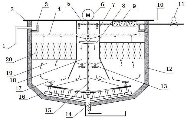
[0023] A simple and efficient integrated coagulation clarification tank, its composition includes: a clarification tank 12, a clarification tank partition wall 7 is installed inside the clarification tank, and the clarification tank is divided into two areas inside and outside, the inner area It is the flocculation area 18, and the outer area is the separation area 19. The water inlet pipe 5 is installed on the top of the clarifier, and the pipeline mixer 9 is installed on the right side of the water inlet pipe. Between the pipeline mixer and the electric regulating valve 11 A flocculant dosing device 10 is installed between them, a primary agitator A8 and a set of secondary agitator B13 are installed sequentially in the flocculation zone from top to bottom, and a mud scraper 16 is installed below the clarification tank, so A group of agitators C17 are respectively installed on the top of the bridge arms of the mud scraper, and a transmission shaft 15 is vertically installed in...
Embodiment 2
[0025] According to the simple and efficient integrated coagulation and clarification tank described in Example 1, the bottom of the clarification tank is equipped with a mud outlet 14, and the inclined pipe device 20 is installed on the upper part of the separation area, the lower part of the water surface 4, and the overflow The mouth 1 and the ring-shaped sump 3 are installed on the upper part of the clarification tank, the maintenance platform is installed on the top of the clarification tank, the upper part of the clarification tank partition wall is in the shape of a cylinder, and the lower part is in the shape of a bell mouth. The outlet diameter of the clarification tank partition wall is 1.5-2 times the inlet diameter.
Embodiment 3
[0027] According to the simple and efficient integrated coagulation and clarification tank described in Example 1, the first-stage agitator A is arranged on the upper part of the flocculation zone, 1.5-2m away from the maintenance platform, and the rotation coverage area of a single impeller is 90-95% of the cross-sectional area of the partition wall, the number of the secondary agitator B is 4 sets, which are arranged at the four corners of the lower part of the flocculation zone, 1- 1.5m, the impeller rotation coverage area is 10-15% of the partition wall area, the third-stage agitator B is arranged on the top of the bridge arm of the mud scraper, the parameters are the same as the second-stage agitator B, and the The inclined pipe device is arranged in the middle and upper part of the separation area, 1.5-2m away from the maintenance platform. If the influent water quality is good or the influent water volume is small, the inclined pipe device may not be installed on the...
PUM
 Abstract
Description
Claims
Application Information
 - R&D Engineer
- R&D Manager
- IP Professional
- Industry Leading Data Capabilities
- Powerful AI technology
- Patent DNA Extraction
Browse by: Latest US Patents, China's latest patents, Technical Efficacy Thesaurus, Application Domain, Technology Topic, Popular Technical Reports.
© 2024 PatSnap. All rights reserved.Legal|Privacy policy|Modern Slavery Act Transparency Statement|Sitemap|About US| Contact US: help@patsnap.com