
Electric nanofiltration ion rectification method for resourceful treatment of high-salinity wastewater

A high-salt wastewater and resource utilization technology, which is applied in separation methods, water/sewage treatment, chemical instruments and methods, etc., can solve the problem that the continuous operation characteristics of the electro-nanofiltration process cannot be effectively reflected, and the separation efficiency of target ions is limited. Ideal screening performance and other issues, to achieve the effect of reducing the requirements of its own characteristics, improving purity and quality, and simple structure

Active Publication Date: 2022-03-01
UNIV OF SCI & TECH OF CHINA
View PDF3 Cites 0 Cited by
  • Summary
  • Abstract
  • Description
  • Claims
  • Application Information

AI Technical Summary

Problems solved by technology

Therefore, in the electrical nanofiltration process, the separation performance of special ions still depends on the screening characteristics of the functional membrane itself, and the unsatisfactory screening performance of the functional membrane also limits the separation efficiency of target ions.
[0005] Similar to the traditional special ion separation process, such as ion exchange, solvent extraction, ion sieve adsorption, etc., the industry needs to achieve the target screening of chloride ions through the coupling and integration of multiple electro-nanofiltration units. At this time, the electro-nanofiltration process Its own continuous operation characteristics cannot be effectively reflected

Method used


Image

  • Electric nanofiltration ion rectification method for resourceful treatment of high-salinity wastewater
  • Electric nanofiltration ion rectification method for resourceful treatment of high-salinity wastewater
  • Electric nanofiltration ion rectification method for resourceful treatment of high-salinity wastewater

Examples


Embodiment 1

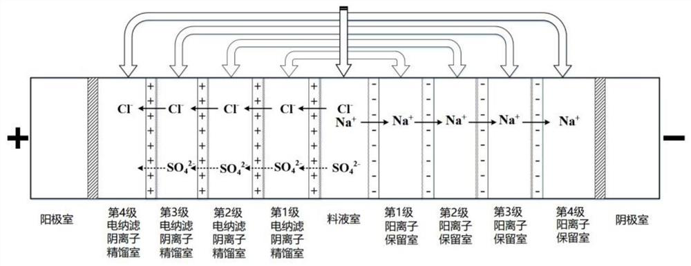
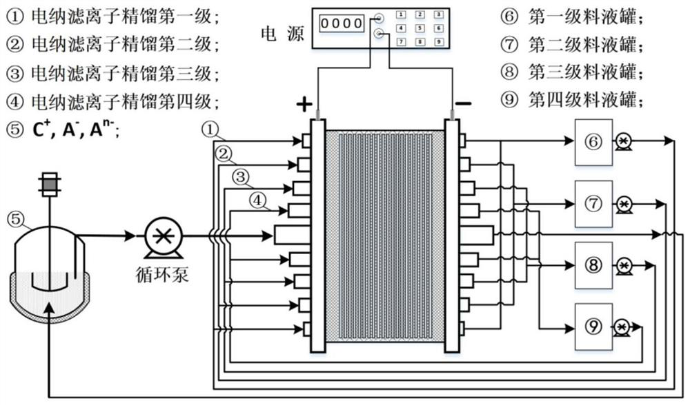
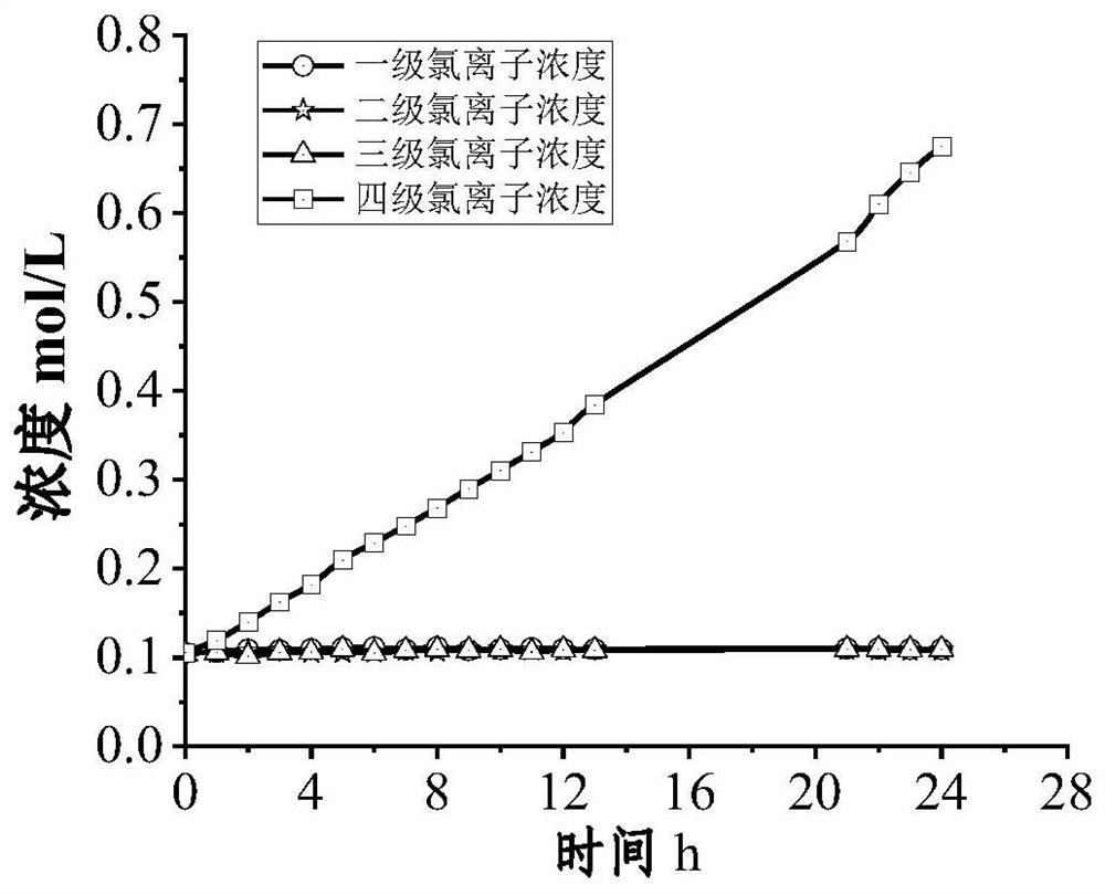
[0050] In this embodiment, the above-mentioned electric nanofiltration ion rectification system is used to treat the simulated high-salt wastewater. The main components of the simulated high-salt wastewater are sodium ions, chloride ions, and sulfate ions. The first-stage electric nanofiltration ion rectification system has one electric nanofiltration ion rectification unit; the first-stage electric nanofiltration anion rectification chamber communicates with the first-stage cation retention chamber, and the circulating flow is driven by a solution-driven pump; the second-stage The electronic nanofiltration anion rectification chamber communicates with the second-stage cation retention chamber, and the circulation flow is driven by a solution-driven pump; the third-stage electric nanofiltration anion rectification chamber communicates with the third-stage cation retention chamber, and the circulation flow is driven by a solution-driven pump ; The fourth-stage electro-nanofiltra...

Embodiment 2

[0054]In this embodiment, the above-mentioned electric nanofiltration ion rectification system is used to treat the simulated high-salt wastewater. The main components of the simulated high-salt wastewater are sodium ions, chloride ions, and sulfate ions. The first-stage electric nanofiltration ion rectification system has one electric nanofiltration ion rectification unit; the first-stage electric nanofiltration anion rectification chamber communicates with the first-stage cation retention chamber, and the circulating flow is driven by a solution-driven pump; the second-stage The electronic nanofiltration anion rectification chamber communicates with the second-stage cation retention chamber, and the circulation flow is driven by a solution-driven pump; the third-stage electric nanofiltration anion rectification chamber communicates with the third-stage cation retention chamber, and the circulation flow is driven by a solution-driven pump ; The fourth-stage electro-nanofiltrat...

Embodiment 3

[0058] In this embodiment, the above-mentioned electric nanofiltration ion rectification system is used to treat the simulated high-salt wastewater. The main components of the simulated high-salt wastewater are sodium ions, chloride ions, and sulfate ions. The first-stage electric nanofiltration ion rectification system has one electric nanofiltration ion rectification unit; the first-stage electric nanofiltration anion rectification chamber communicates with the first-stage cation retention chamber, and the circulating flow is driven by a solution-driven pump; the second-stage The electronic nanofiltration anion rectification chamber communicates with the second-stage cation retention chamber, and the circulation flow is driven by a solution-driven pump; the third-stage electric nanofiltration anion rectification chamber communicates with the third-stage cation retention chamber, and the circulation flow is driven by a solution-driven pump ; The fourth-stage electro-nanofiltra...


PUM

PropertyMeasurementUnit
areaaaaaaaaaaa

Abstract

The invention discloses an electric nanofiltration ion rectification method for resourceful treatment of high-salinity wastewater, which comprises the following steps: firstly, arranging an electric nanofiltration ion rectification system which is formed by sequentially laminating a plurality of cation exchange membranes and electric nanofiltration membranes according to the principle of'the same kind and the same side 'and then adding a runner separation net and a sealing gasket; chloride ions are respectively and selectively screened by a plurality of electric nanofiltration membranes, meanwhile, impurity anions are selectively blocked, and finally, through n-stage selective separation, a selectivity coefficient between the chloride ions and the impurity anions is subjected to stage amplification, so that efficient extraction of sodium chloride is realized in a single electric nanofiltration ion rectification membrane assembly. The selectivity coefficient of the chloride ions and the sulfate ions is determined by the number of the electric nanofiltration membranes used in an overlapped mode, the requirement for the characteristics of a special membrane is greatly lowered, and the purity and quality of a salt separation product of the high-salinity wastewater are greatly improved.

Description

technical field [0001] The invention belongs to the field of electric-driven membrane separation, and in particular relates to an electric nanofiltration ion rectification method for high-salt wastewater resource treatment. Background technique [0002] Special ion separation is an important chemical separation technology, which occupies an important position in the field of zero discharge and resource utilization of high-salt wastewater. In many production fields such as printing and dyeing, papermaking, chemical industry and pesticides, and oil and natural gas collection and processing, a large amount of high-salt wastewater with a mass fraction greater than 1% will be produced. In addition to organic matter, these wastewater also contain Cl - , SO 4 2- 、Na + and other salts. This type of high-salt wastewater has a high salt content, and is much more harmful to the environment than urban domestic sewage. The country puts forward higher requirements for the treatment o...

Claims


Application Information

Patent Timeline
Patent Type & Authority Applications(China)
IPC IPC(8): C02F1/469C01D3/06C01D3/14C02F101/12C02F101/10
CPCC02F1/469C02F1/4693C01D3/14C01D3/06C02F2101/12C02F2101/101
Inventor 徐铜文葛亮蒋晨啸陈秉伦
Owner UNIV OF SCI & TECH OF CHINA
Learn More