Array scanning super-resolution microscopic imaging device, method and equipment based on multiple signal classification algorithm and storage medium
A multi-signal classification and microscopic imaging technology, applied in the field of laser scanning microscopic imaging, can solve the problems of difficulty in improving lateral resolution and low image acquisition rate, and achieve the effect of improving lateral imaging resolution and imaging speed.
- Summary
- Abstract
- Description
- Claims
- Application Information
AI Technical Summary
Problems solved by technology
Method used
Image
Examples
Embodiment approach 1
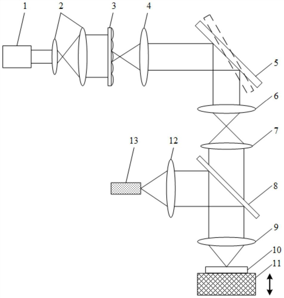
[0037] Such as figure 1 As shown, an array scanning super-resolution microscopic imaging device based on a multiple signal classification algorithm includes a laser light source 1, and a beam expander system 2, a microlens array 3, a collimator lens 4, and Scanning galvanometer 5 , scanning lens 6 , tube mirror 7 , dichroic mirror 8 , objective lens 9 , fluorescent sample 10 , stage 11 , collecting lens 12 and CCD camera 13 .
[0038] The microlens array 3 and the scanning galvanometer 5 constitute a scanning system. The focused spot array generated by the microlens array 3 is used as a point light source array, and the scanning galvanometer 5 changes the beam deflection angle so that the focused spot array scans the fluorescent sample 10 .
Embodiment approach 2
[0040] An array scanning super-resolution microscopic imaging method based on a multiple signal classification algorithm, comprising the following steps:
[0041] Step 1. Obtain a low-resolution image sequence of the fluorescent sample 10 by using an array scanning super-resolution microscopic imaging device.
[0042]The light beam emitted by the laser light source 1 passes through the beam expander system 2 to form parallel light incident on the microlens array 3, forms a point light source array on the focal plane of the collimator lens 4, and passes through the scanning galvanometer 5, scanning lens 6, tube mirror 7, The dichroic mirror 8 and the objective lens 9 focus on the surface of the fluorescent sample 10 to be measured, and the scanning galvanometer 5 changes the beam deflection angle to realize the two-dimensional array scanning of the fluorescent sample 10, and the fluorescence emitted by the fluorescent sample 10 passes through the objective lens 9, the dichroic ...
PUM
 Abstract
Description
Claims
Application Information
 - R&D
- Intellectual Property
- Life Sciences
- Materials
- Tech Scout
- Unparalleled Data Quality
- Higher Quality Content
- 60% Fewer Hallucinations
Browse by: Latest US Patents, China's latest patents, Technical Efficacy Thesaurus, Application Domain, Technology Topic, Popular Technical Reports.
© 2025 PatSnap. All rights reserved.Legal|Privacy policy|Modern Slavery Act Transparency Statement|Sitemap|About US| Contact US: help@patsnap.com


