
A super-resolution structure detection array confocal fluorescence imaging device and its imaging method

An imaging device and detection array technology, applied in fluorescence/phosphorescence, material excitation analysis, etc., can solve the problems of low imaging rate, unclear confocal imaging, difficulty in improving the resolution of confocal microscopy technology, etc., to improve imaging rate, measure The effect of speed reduction and OTF bandwidth increase

Active Publication Date: 2019-02-05
HARBIN INST OF TECH
View PDF6 Cites 0 Cited by
  • Summary
  • Abstract
  • Description
  • Claims
  • Application Information

AI Technical Summary

Problems solved by technology

[0005] The purpose of the present invention is to solve the problems that the resolution of the existing confocal microscopy technology is difficult to improve, the imaging rate is low, and the confocal imaging is not clear

Method used


Image

  • A super-resolution structure detection array confocal fluorescence imaging device and its imaging method
  • A super-resolution structure detection array confocal fluorescence imaging device and its imaging method
  • A super-resolution structure detection array confocal fluorescence imaging device and its imaging method

Examples


Embodiment Construction

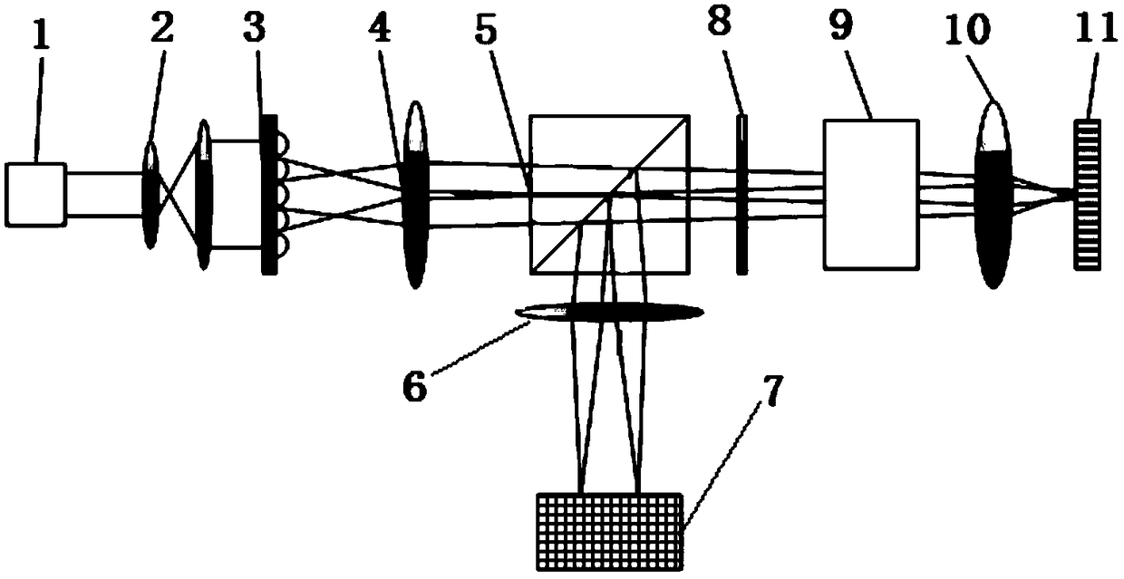
[0030] The specific embodiment of the present invention is described in conjunction with the accompanying drawings. A super-resolution structure detection array confocal fluorescence imaging device of the present invention includes a laser light source 1, and a collimating beam expander 2 and a microlens are sequentially placed along the light propagation direction of the laser light source 1. Array 3 , collimating lens 4 , dichroic prism 5 , 1 / 4 wave plate 8 , scanning system 9 , illumination objective lens 10 , fluorescent sample 11 , collecting lens 6 and CCD detector 7 .

[0031] The scanning system includes a scanning galvanometer, and the scanning galvanometer scans the object plane of the fluorescent sample by changing the beam deflection angle.

[0032] An imaging method based on the super-resolution structure detection array confocal fluorescence imaging device, comprising the following steps:

[0033] Step 1. The light intensity distribution on the detection surface ...


PUM


Abstract

The invention provides a super-resolution structure detection array confocal fluorescence imaging device and an imaging method thereof, relating to imaging devices and imaging methods thereof and aiming to solve the problems that the resolution of the existing confocal limiting technology is difficult to increase and confocal images are not clear. The device comprises a laser source, wherein a collimator and beam expander, a beam splitter prism, a 1 / 4 wave plate, a scanning system, an illumination objective, a fluorescent sample, a collecting lens and a CCD (charge coupled device) detector are arranged along the ray propagation direction of the laser source in sequence. The device has the effects that integration is carried out on a detection plane to change the light sensitivity of a corresponding detecting location; the OTF (optical transfer function) bandwidth of a system is expanded; the spatial cut-off frequency of a confocal fluorescence imaging system is improved and the spatial frequency domain bandwidth is expanded, thus obviously improving the lateral resolution of the imaging system; and the device is applicable to the measurement field of industrial topographic imaging.

Description

technical field [0001] The invention relates to an imaging device and an imaging method thereof, in particular to a super-resolution structure detection array confocal fluorescence imaging device and an imaging method thereof, belonging to the technical field of optical precision measurement. Background technique [0002] Optical microscopy is a long-established and important non-destructive technique widely used in fields such as biology and materials science. Confocal microscopic measurement technology is a three-dimensional optical microscopy technology suitable for micron and submicron scale measurement. The tomographic capabilities of reflective confocal microscopy systems make them important in the field of 3D imaging. [0003] In the mid-to-late 1950s, the confocal microscope was invented by Minsky. In 1977, C.J.R. Sheppard and A.Choudhury first clarified that the confocal microscope system under the action of the dot pinhole mask, at the expense of the field of view...

Claims


Application Information

Patent Timeline
Patent Type & Authority Patents(China)
IPC IPC(8): G01N21/64
Inventor 邹丽敏王宝凯张甦谭久彬
Owner HARBIN INST OF TECH
Learn More