Storage tank for large-scale fused salt energy storage

A large-scale, molten salt technology, applied in tank trucks, large containers, containers, etc., can solve the problems of complex systems, poor reliability, increased failure points, small tank volume, etc., to save tank material costs, reduce failure points, System simple effect

Pending Publication Date: 2022-03-04
HARBIN TURBINE AUX EQUIP ENG
View PDF0 Cites 1 Cited by
  • Summary
  • Abstract
  • Description
  • Claims
  • Application Information

AI Technical Summary

Problems solved by technology

[0003] The present invention solves the problem that the existing molten salt energy storage storage tank has a high freezing point temperature of the molten salt. In order to avoid the condensation of the molten salt in the pump, the pump is arranged on the top of the tank. When the molten salt heat storage double tanks are in operation, the liquid level will change up and down , the lowest point is close to the bottom of the tank, so the pump shaft of the molten salt pump needs to be longer and extend below the liquid surface. Since the pump shaft cannot be too long, the tank body cannot be too high, resulting in a smaller volume of the tank body , which leads to the problem of smaller volume, and other single-tank schemes, additional molten salt tanks and their connecting pipes and heat tracing devices are required, which increases the number of failure points, and the system is complicated and reliable. A large-scale Storage tanks for molten salt energy storage

Method used


Image

  • Storage tank for large-scale fused salt energy storage
  • Storage tank for large-scale fused salt energy storage
  • Storage tank for large-scale fused salt energy storage

Examples


specific Embodiment approach 1

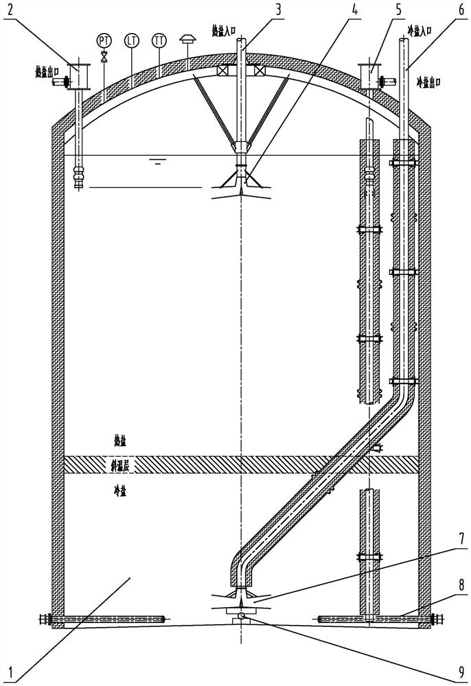
[0036] DETAILED DESCRIPTION One: Combination figure 1 The present embodiment described embodiment, the embodiment of the present embodiment for a large-scale tank molten salt storage tank 1 includes a heat pump 2 salts, salts heat pipe system 3, a hot plate 4 cloths salt, cold saline pumps 5, 6 cold saline piping system, the cold plate salt cloths 7, the electric heater 8, the cold salt cloth supporting unit 9;

[0037] Roof body 1 dome is a spherical cap, on top of the tank body 1 is provided with pressure meters, level meters, temperature meter, and a safety relief unit heat pump salts, salts heat pipe system, the pump and cold saline cold saline pipe system, the pump and the hot salt disposed close to the tank wall, which inlet is provided in a position near the liquid level inside the tank, and heat pipe system disposed salt tank top center position, the outlet of a hot plate is connected cloths salt, cold saline a pump disposed close to the tank wall, that the suction tube in...

specific Embodiment approach 2

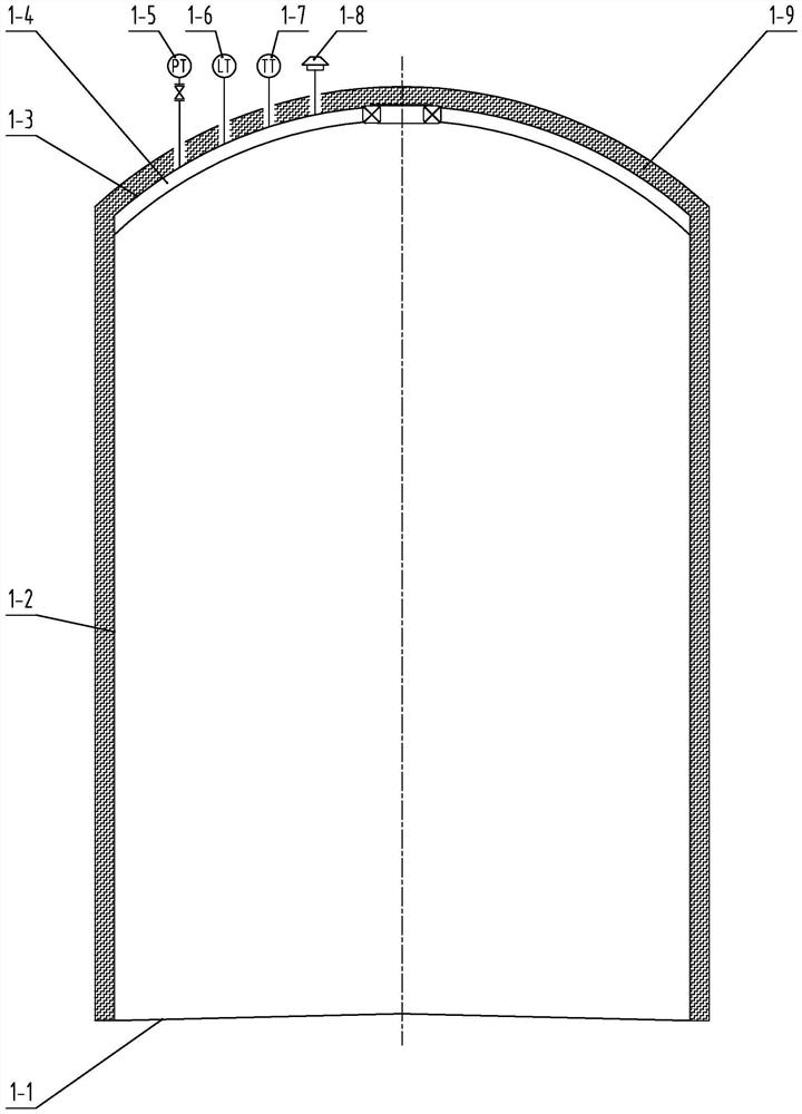
[0043] DETAILED DESCRIPTION 2: Combination figure 2 The present embodiment described embodiment, the present embodiment is further limited to specific embodiments of the tank according to a present embodiment one embodiment of the molten salt storage tank for large-scale, the can body 1 1-1 comprises a tank bottom, the tank wall 1-2, 1-3 roof, roof steel support 1-4, pressure meters 1-5, 1-6 level meter, temperature meter 1-7, safety relief means 1-8 and 1-9 tank insulation means, the upper portion of the tank bottom welded 1-1 1-2 tank wall, the tank wall welded upper roof 1-2 1-3, 1-4 tank top outer edge of the steel support welding the interior tank walls 1-2, an upper portion of the lower tank top surface weld 1-3, 1-5 equipped with a pressure meter, a liquid level meter roof 1-3 1-6 1-7 temperature meter, safety relief device 1-8, 1-3 and 1-2 outside the tank wall provided with roof tank insulation means 1-9

specific Embodiment approach 3

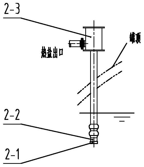
[0044] Specific Embodiment 3: Combination image 3 The present embodiment described embodiment, the present embodiment is further limited to specific embodiments of the tank according to a present embodiment the one storage tank for molten mass, said heat pump salts 2 comprises a suction pipe heat salts 2-1, 2-2, and a power head means 2-3, 2-3 power means connected to one end of the pump head 2-2, the other end of the salts of the suction pipe and the heat pump head 2-2 2-1 connected to the top of the pump head is arranged close to a position near the liquid level, and thus without a long shaft.


PUM


Abstract

The invention discloses a storage tank for large-scale fused salt energy storage, and relates to the technical field of fused salt energy storage. In order to solve the problems that according to an existing fused salt storage tank, due to the fact that the freezing point temperature of fused salt is high, when the fused salt heat storage double tanks operate, the liquid level can change vertically, and the lowest liquid level is close to the bottom of the tank body, a pump shaft of a fused salt pump needs to be long and extends below the liquid level, and due to the fact that the pump shaft cannot be made to be too long, the tank body is limited to be too high. The technology that hot salt with low density is located on the upper portion, cold salt with high density is located on the lower portion, and a temperature gradient layer, namely a thermocline layer is arranged in the middle is adopted, through a salt distributor and a pipeline system, during heat storage, hot salt passes through a hot salt pipeline system and enters a tank body through a hot flat plate type salt distributor, cold salt is pumped out of the tank body through a cold salt pump, and the thermocline layer gradually moves downwards; the heat storage process is finished; during heat release, hot salt is pumped out of the tank body through a hot salt pump, cold salt enters the tank body from the cold flat plate type salt distributor through a cold salt pipeline system, and the thermocline gradually moves upwards. The method is suitable for the technical field of high-temperature fused salt energy storage.

Description

Technical field [0001] The present invention relates to the field of molten salt storage, and more particularly to a storage tank for a large-scale molten salt. Background technique [0002] The energy storage system is a discontinuous problem that solves wind energy, solar energy, and realizes the effective means of power grid picking peaks, promoting the effective means of cleaning energy, and has positive significance for achieving "double carbon" goals. At present, common energy storage modes include electrochemical energy storage, pumping energy storage, compressed air storage, melt salt storage and flywheel energy storage, which can achieve only a large-scale storage and compressive air energy storage, but The two are also subject to local conditions such as geography, season, and cannot be widely used. High-temperature melting salt heat is a technical solution that is often used in a photothermal power generation system. It is also a more mature scheme that stores high-qua...

Claims


Application Information

Patent Timeline
Patent Type & Authority Applications(China)
IPC IPC(8): B65D88/74B65D90/00F28D20/00
CPCB65D88/744B65D90/00F28D20/0034Y02E60/14
Inventor 赵宇炜洪增元卢日时姚亮程方
Owner HARBIN TURBINE AUX EQUIP ENG
Why Eureka
Try Eureka