Miniaturized broadband low-frequency noise elimination pipeline

A sound-absorbing tube and low-frequency noise technology, which is applied in the direction of sound-emitting devices and instruments, can solve the problems of large space occupation, and achieve the effects of structural optimization, noise energy reduction, and small space occupation

Active Publication Date: 2022-03-11
中科建声(苏州)新材料科技有限公司
View PDF14 Cites 0 Cited by
  • Summary
  • Abstract
  • Description
  • Claims
  • Application Information

AI Technical Summary

Problems solved by technology

However, in order to achieve low-frequency sound insulation, multiple resonators need to be connected in series and parallel in the impedance compound muffler, which takes up a lot of space.

Method used


Image

  • Miniaturized broadband low-frequency noise elimination pipeline
  • Miniaturized broadband low-frequency noise elimination pipeline
  • Miniaturized broadband low-frequency noise elimination pipeline

Examples


Embodiment 1

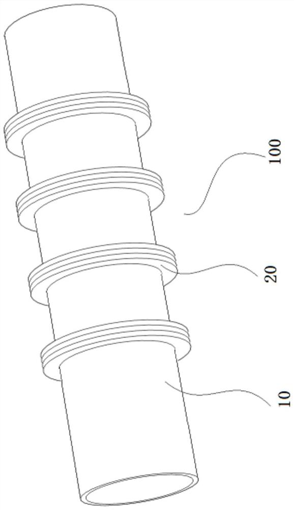
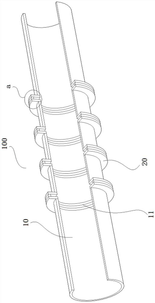
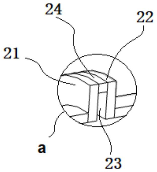
[0041] Such as Figure 1~3 As shown, this embodiment provides a miniaturized broadband low-frequency noise reduction pipeline 100 (hereinafter referred to as the noise reduction pipeline 100), the noise elimination pipeline 100 includes a pipe body 10 and at least one sound-absorbing units 20 , and at least one sound-absorbing unit 20 is arranged at equal intervals along the axial direction of the pipe body 10 . Wherein, the pipe body 10 is provided with at least one slot 11 along its side wall, and the sound absorption unit 20 includes a first plate 21 and a second plate 22 connected to the side walls on both sides of any slot 11, the first plate The part 21 cooperates with the second plate part 22 to form a sound-absorbing channel 23, one end of the sound-absorbing channel 23 communicates with the inner cavity of the pipe body 10, and the other end communicates with the outside.

[0042] It should be noted that the muffler pipeline in this embodiment is mainly used to block...

Embodiment 2

[0056] On the basis of Embodiment 1, this embodiment further provides a muffler pipeline 100, such as Figure 4 As shown, the difference compared with Embodiment 1 is that the second plate 22 in the muffler pipeline 100 includes an extension 221 extending to the inner cavity of the pipe body 10, and the sound absorption unit 10 also includes a The arc-shaped wall 25 in the inner cavity is connected to the extension part 221 , and the extension part 221 , the arc-shaped wall 25 , and the inner wall of the tube body 10 cooperate to form a side wall channel 26 . Continue to refer to Figure 4 As shown, when the airflow and sound waves in the pipe body 10 flow in the direction indicated by the arrow, part of the sound waves will flow into the side wall flow channel 26, thereby entering the sound absorption channel 23 for low-frequency sound absorption.

[0057] This embodiment does not limit the connection position between the extension part 221 and the arc-shaped wall 25, but in...


PUM


Abstract

The invention discloses a miniaturized broadband low-frequency noise elimination pipeline which comprises a pipe body and at least one sound absorption unit, the pipe body is provided with at least one groove along the side wall of the pipe body, each sound absorption unit comprises a first plate and a second plate which are connected with the side walls of the two sides of any groove, and the first plate and the second plate are matched to form a sound absorption channel. One end of the sound absorption channel communicates with an inner cavity of the pipe body, the other end of the sound absorption channel communicates with the outside, and the maximum distance between the first plate and the second plate is smaller than the wavelength of target low-frequency noise; according to the silencing pipeline, the sound absorption unit is arranged on the side wall, a sound absorption channel is formed, low-frequency noise is effectively blocked, broadband sound insulation is achieved, additional equipment such as a resonator does not need to be arranged in an inner cavity of the pipe body, the occupied space is small, sound insulation is achieved without relying on resonance, the problem of frequency deviation failure caused by the airflow Doppler effect is avoided, and the noise reduction effect is good. And the sound insulation effect stability is good.

Description

technical field [0001] The invention relates to the field of noise reduction, in particular to a miniaturized broadband low-frequency noise reduction pipeline. Background technique [0002] The ventilation duct / exhaust duct forms an acoustic waveguide structure, and the noise generated by the equipment tends to travel along the duct, so they become an important path for the transmission of mechanical noise. Under normal circumstances, it is necessary to add some appropriate structures in the pipeline to absorb or block the sound waves. A common treatment method is to use a muffler structure. [0003] At present, the commonly used mufflers are mainly divided into three types: resistance muffler, resistive muffler and impedance composite muffler. The resistance muffler often uses a large amount of porous materials and is laid along the pipeline. For the noise in the middle and high frequency bands, the resistance muffler can achieve a large amount of sound absorption to achie...

Claims


Application Information

Patent Timeline
Patent Type & Authority Applications(China)
IPC IPC(8): G10K11/16
CPCG10K11/16
Inventor 左洪运毕亚峰
Owner 中科建声(苏州)新材料科技有限公司
Why Eureka
Try Eureka